Part 1 - Initial Development
The "Fred Park" Table
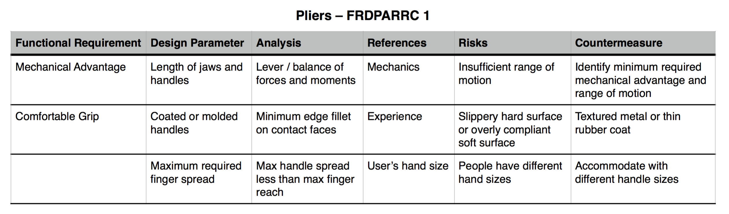
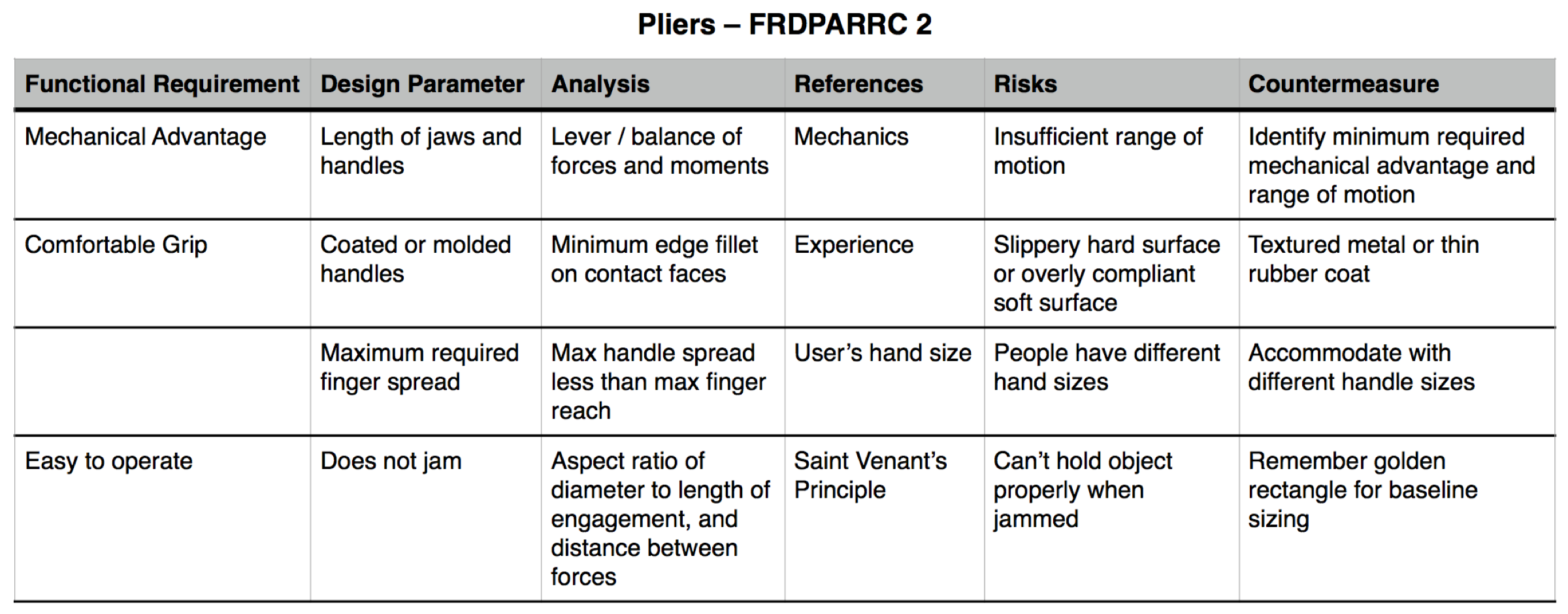
The first step in considering a design is identifying its functional requirements, a process that goes in hand with the various parameters presented in the FRDPARRC table. These letters stand for Functional Requirements, Design Parameters, Analysis, References, Risks, and Countermeasures.
By the way, that name is quite a mouthful, right? I just call it the "Fred Park" table - much easier to pronounce!
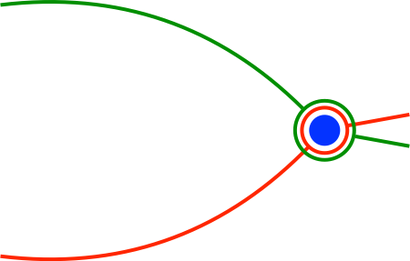
The Stick Figure
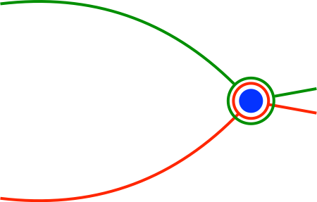
Next, a simple stick figure helps illustrate the device. From here, it becomes easier to consider the forces and interactions that will enable it or break it.
The Free Body Diagrams
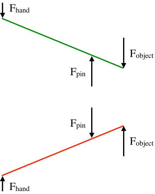
Did I mention forces just a moment ago? Right, and here they are again! Free Body Diagrams (FBDs) are very helpful tools.
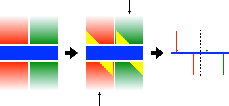
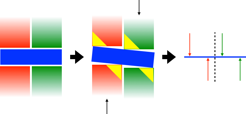
Things get very interesting when looking at the loads on the pin. In order to get the simplified FBD on the right of the progression below, consider the way the pin would twist and bend as the handles press in opposite directions. With the loads shown in the center illustration, the yellow triangles represent the local hotspots - the areas that would bear this load.
The Mathy Stuff
As part of the detailed analysis, some calculations will be needed. For these, the equations below will be most helpful.
First off, take a look at the balance of forces. Note that the FBDs above show vertical forces only, so I am giving the equation for the forces on y.

Next, check the balance of moments.

With those two out of the way, now it's time to consider material properties. First, check the bending stress.

Then, check the shear stress.

The Sliding Interface
For a sliding interface between elements, it's important to go beyond the basic internal stress analysis. The effect of contact stresses may alter the nature of the interface, for example. Additionally, sliding interfaces (such as bushings or bearings) are subject to the PV load factor - that is, contact pressure versus sliding speed - which affects the machine's lifespan.
The Errors
Errors that may affect this device include differences in diameter between the pin and the handle parts, or an inadequate aspect ratio between the pin diameter and the length of engagement with each handle.
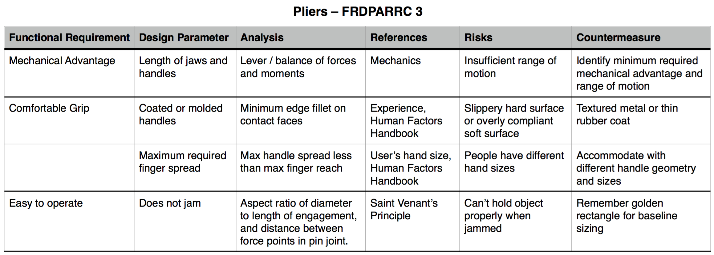
The FRDPARRC Table, UPDATED
It's always good to remember your previous work. You learn things along the way, and might want to integrate the new data points to your design.
Part 2 - PREP
Team Review and Feedback
First things first - looks like I reversed the direction of my pliers in the sketch posted in Part 1, and forgot to add labels for the lever arms to be used in the analysis. The updated images will appear in Part 3.
Next, Aaron suggested a reference for my FRDPARRC table: the Human Factors Handbook. He also asked about mechanical advantage when accommodating different hand sizes - this I would think of addressing with handle geometry as well as sizing.
On the section about the design analysis, Julian suggested making a note of why the geometric simplification is valid, and how the distributed stress sections on the pin joint can be regarded as point loads for a first approximation.
Alright, let's see about addressing those points then!
Part 3 - Rework & Updates to Part 1
The FRDPARRC Table, UPDATED [again!]
The first step in considering a design is identifying its functional requirements, a process that goes in hand with the various parameters presented in the FRDPARRC table. These letters stand for Functional Requirements, Design Parameters, Analysis, References, Risks, and Countermeasures.
By the way, that name is quite a mouthful, right? I just call it the "Fred Park" table - much easier to pronounce!
The Stick Figure
As mentioned in Part 2, I managed to reverse my pliers when preparing the images for Part 1. For the sake of clarity and consistency, let's make sure all sketches and FBDs agree. First off, here's the corrected stick figure:
The Free Body Diagrams
Now, when preparing the material the first time around, I had a mental picture of what each part would look like and which points I would use as reference when performing the analysis. But, people can't read my mind - for that matter, future me won't do much better either. So, it's important that all thoughts are properly documented. In the case of my FBDs, that means including the lever arms used in the moment equation.
Also, as Julian suggested, here's a quick note on the geometric simplification: doing a first-order approximation with the straight handles will be much easier and will land you in the right order of magnitude, decently close to the real solution if the final shape isn't terribly crazy. The effect of that nice curvy handles in the sketch can be revisited for more detailed analysis later on.
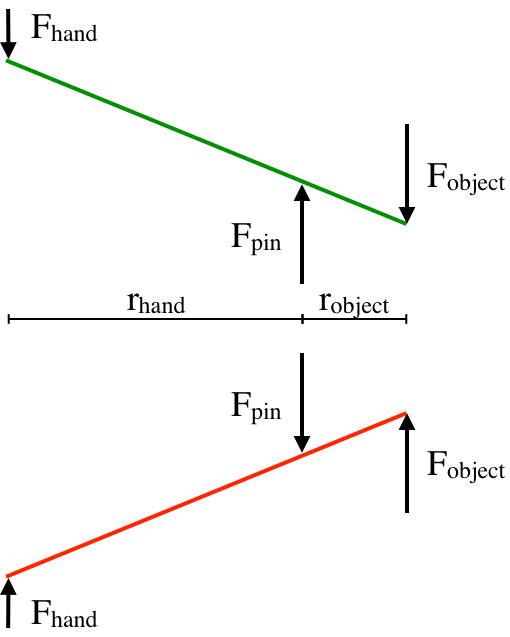
Next, I did mention things would get interesting when looking at the pin. After discussing with my peers, it became clear that I needed to help the reader visualize how the pin might move between the handles. This, in turn, makes it easier to understand why the loads behave as distributed loads starting from each of the edges on the pin joint. So, these load distributions are represented in the image below as yellow triangles, just as they were in Part 1. However, the the handles are slightly offset from their starting position, and the pin has rotated accordingly.
It follows that a load distribution such as this may be represented as a concentrated load (or point load). As for the proper placement of these loads, the net effect of each force couple must first be derived from the handle FBD. With a known F_pin, and using the equations for balance of forces and moments, we can calculate the magnitude and position of each point load. This is, of course, under the assumption that we model the load distribution as a linear function throughout the length of the interface. In other words, the triangles in the red section both have the same slope, and the sum of their bases is equal to the thickness of the handle at the pin joint.
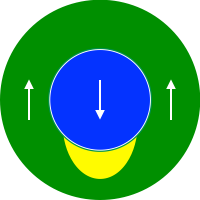
An element that was missing in Part 1 was the sideview for this pin loading. This illustration goes hand in hand with the load distributions shown above, where only part of the pin (and not its full diameter) can effectively carry the load. In particular, this becomes relevant when looking at contact stresses, since the pin or its hole might deform and affect the behavior of the joint.
The Mathy Stuff
Just a small change here, in case anyone decides to read the equation as a cross-product instead of a good ol' multiplication. I did leave the negative in place tho, showing that the resulting moments go in opposite directions and can balance each other.

The Sliding Interface
Here, I'll add a quick mention of Hertzian contact stresses by name. While mentioned briefly in Part 1, it's good to remember these names. This relates to what I mentioned earlier in the FBD section, about the pin joint sideview being important. The larger the area capable of bearing the loads from the pin, the lower the contact stress. If too large, this pressure may deform the joint feature.
The Errors
Other errors I didn't mention in Part 1 include geometric faults such as a variable diameter along the length of the pin, or a bent pin. As for parasitic errors, it is also important to consider how the handles or jaws might bend and twist due to the various loads.