Part 1 - Status Update on PUP Series
PUP 8 - Resumed (*)
On the last update I posted under PUP 8, I had just had some issues with post-processing of tool paths for CNC machining. After doing some looking around, I managed to pull a ".cps" file I had received from Aaron to get the ProtoTRAK reading GCode from HSMworks correctly. Since I've been using Fusion360 for this project, and the integrated CAM module uses the same HSMworks engine, the same post processor file got me back in the game without having to switch CAD software at the last minute. Good!
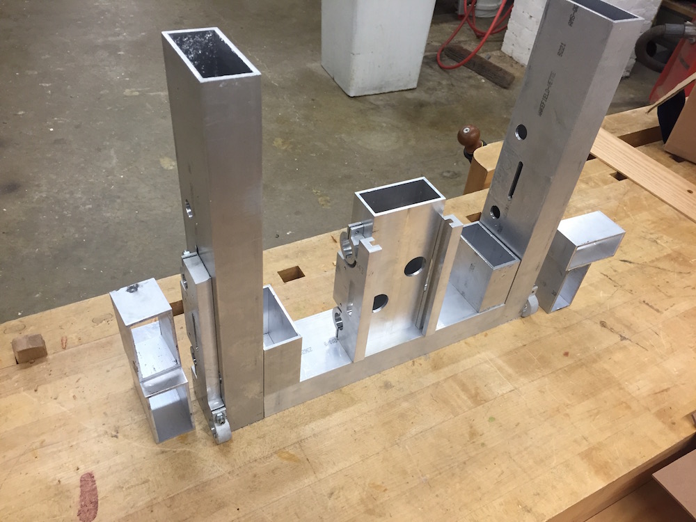
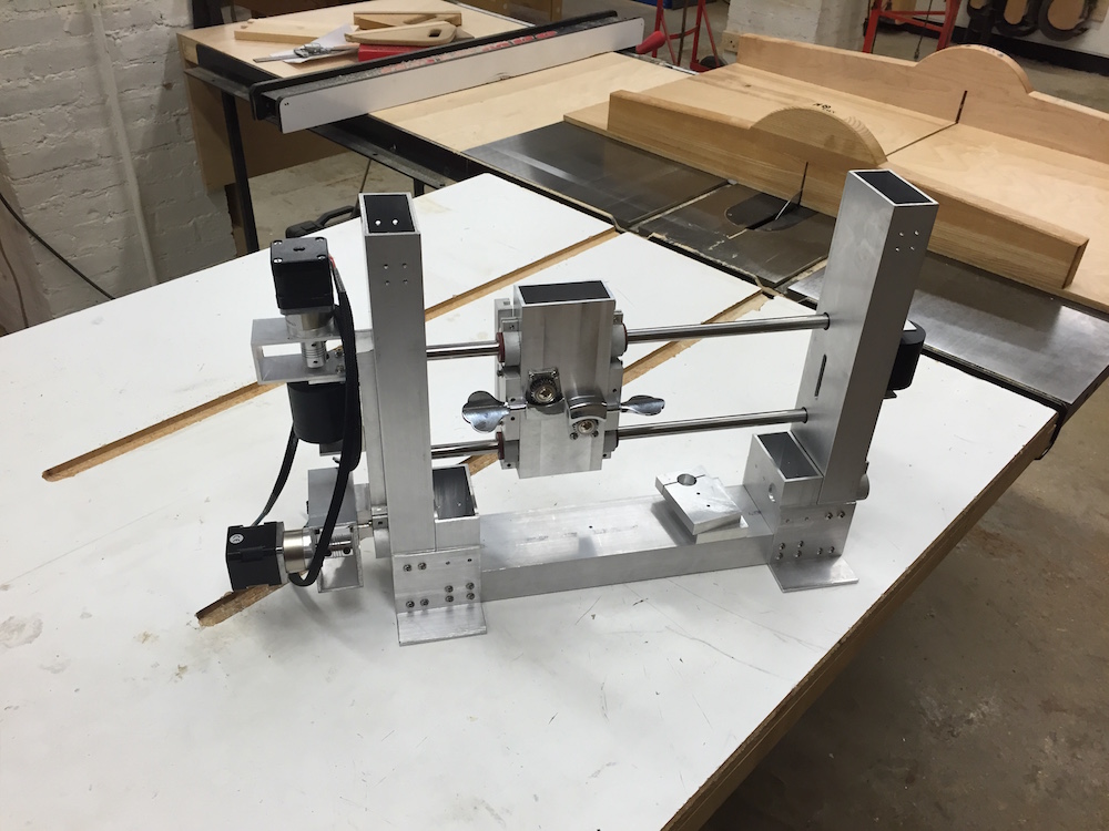
From there on, the past few weeks have been dedicated to machining in various forms - from the necessary post-machining on the waterjetted plates to cutting and squaring stock for the frame components, to making the floating blocks for the cable clamps. By the end of April, about a week ago, I had enough parts to make a general layout that resembled the CAD model:
Before geting to the stage shown above, I had some challenges with post-machining of the carriage plates. In order to bore out the bearing clamps, I had to first get the screw holes machined and locked during the operation. I also had to make sure the part was properly fixtured while on the mill. Despite the attention given to these details, I still had an end-mill pull the follower clamp on one of the plates and introduce a gap on the surface. Turns out the fixturing I had used was not stiff enough, so I had to rearrange the setup, and then adjust my feed and speed rates on the culprit toolpath before trying again.
After getting a clean pass on the part and measuring the resulting bore, I discovered that the toolbit I had used during this second attempt was significantly undersized. That is, the 1/4" end-mill I had on the machine actually measured less than 0.24" - in fact, I created a new tool on my CAM software and, looking at the diameter listed there, it measured 0.232" on the calipers. Big deal when trying to get decent tolerances! A little bit of legwork, and problem solved, tho.
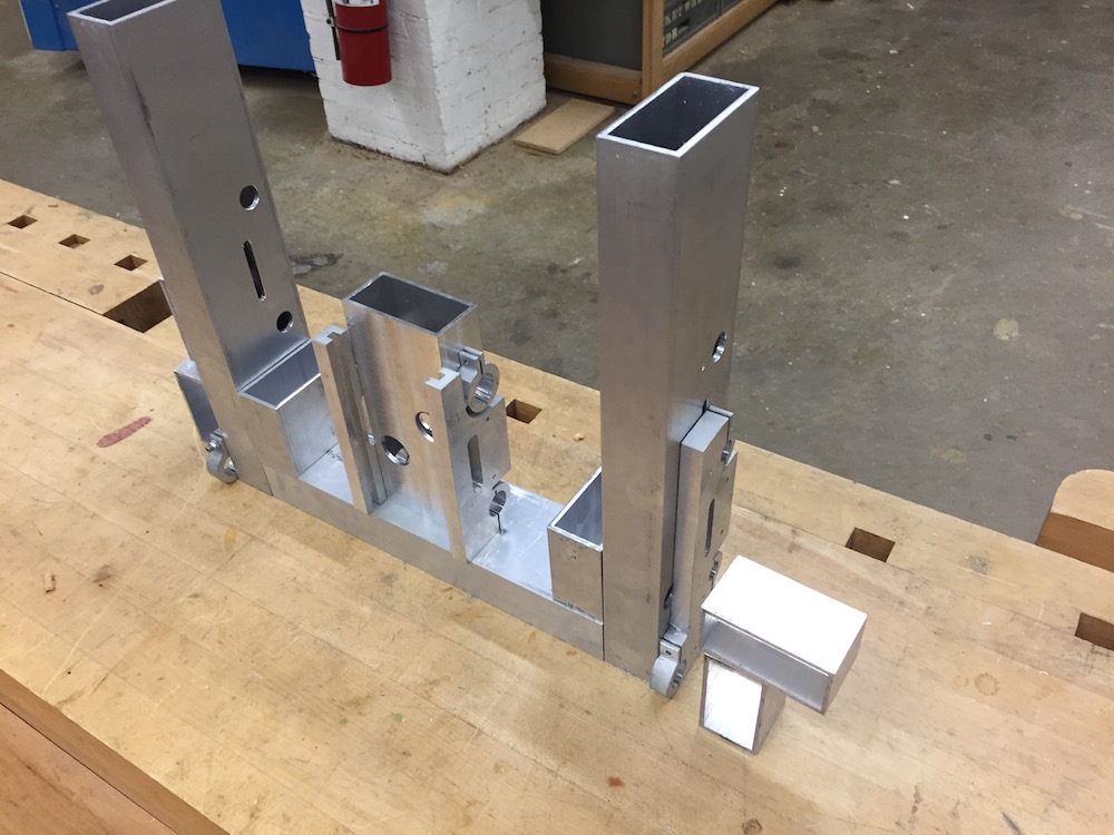
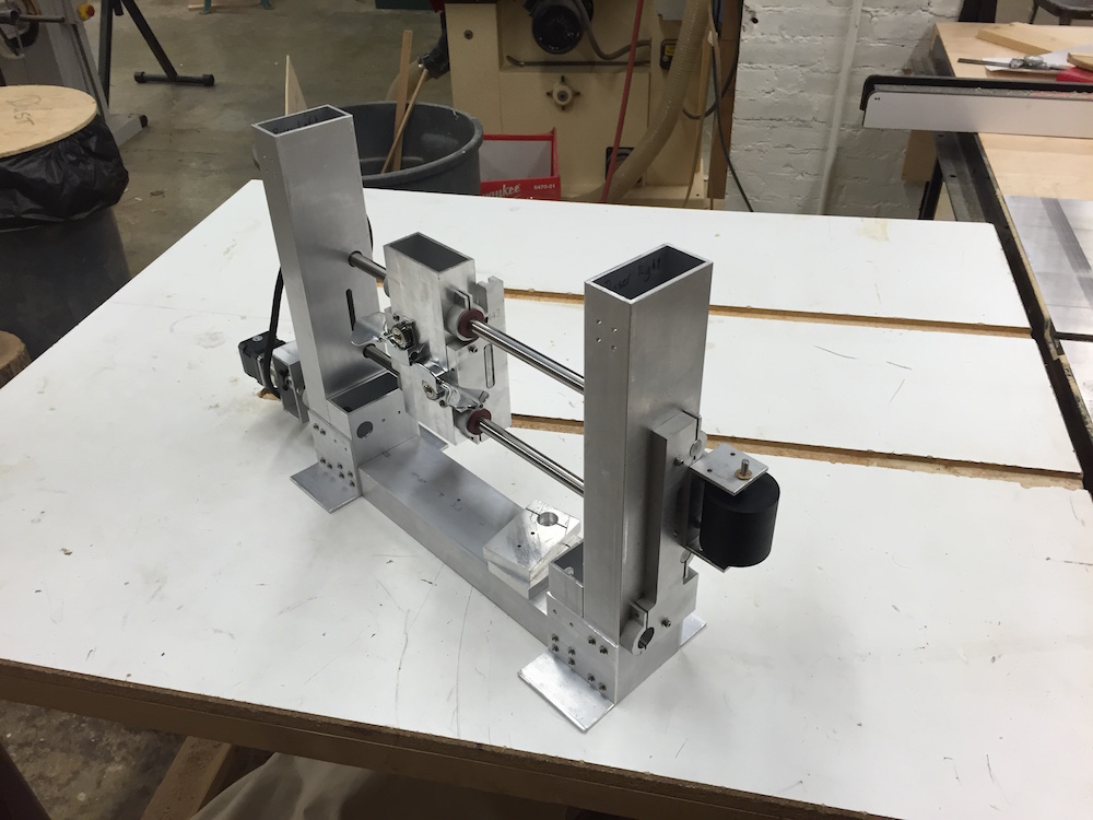
It was troublesome to have these issue, surely, but in the end it paid off to learn from it and address it with the tools at hand - here's the same layout with the bushings installed on the carriage plates:
PUP 9 - Machine Detailing and Structure Bracing
As part of the structural frame, I needed to add some bracing to stiffen the riser assembly. While the preferred approach would be to add some X-bracing between the risers, covering the main diagonals, I had some trouble finding a good way to fit the runners without interfering with the tool holder and Z-axis carriage on the front, or the tuning machines for the cable drive, on the back.
I also needed to work out a good way to connect the tubes together. Plus, given that the machine is designed for a vertical configuration, I needed to make sure it wouldn't tip over. Since my Z-axis remains in the list of items for future work, I don't know the exact location of the center of mass. Furthermore, I have been looking into adding a baseplate on which I can eventually mount the electronics enclosure and perhaps add a small display.
As such, I opted for a set of connection angles on the bottom corners, and a set of plates to a top spacer tubebetween the risers. While the corner gussets won't provide the same stiffness as the X-bracing or even K-bracing, I expect it will be enough for this application. For that matter, the counter-argument is also valid - the added compliance from using the corner plates may grant me enough room to adjust the structure to the rails, and then set the final arrangement thru surface replication with epoxy during the final assembly.
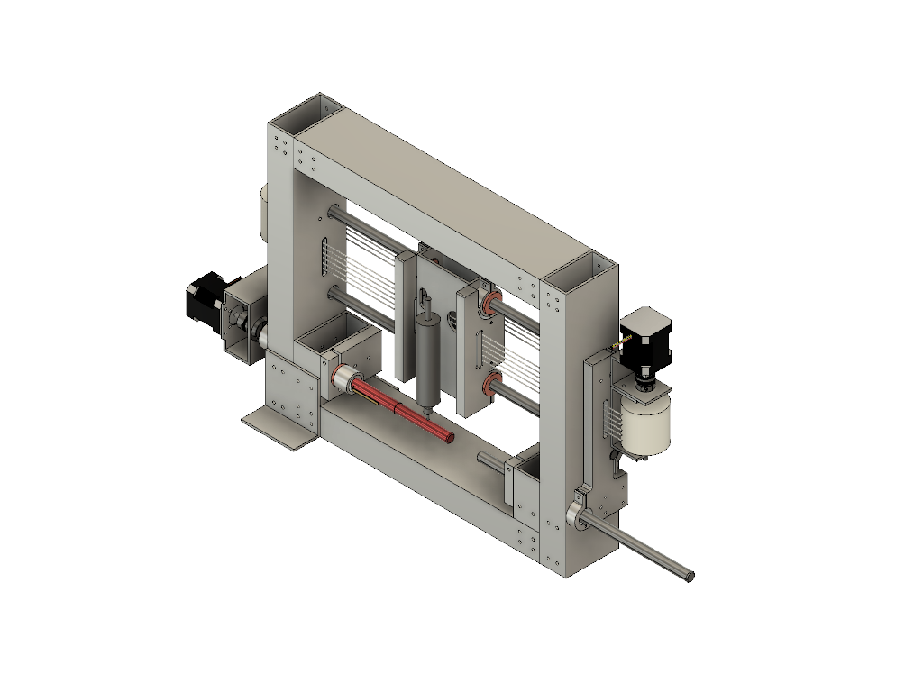
Here's a rendering of the CAD model with the added corner plates and top spacer tube. Note that the top connection plates are not shown, and the angles at the lower corners are only shown for the left-side joint.
Part 2 - PREP
Team Review and Feedback
For the most recent rounds of PREP, I talked to Aaron and Julian about my ideas for holding together the frame's joints, and bracing. They seemed supportive of my thought process regarding the corner connections. Beyond that, our focus has been on fabrication, so not too much to talk about just yet. Julian did have a very interesting experience with his flexure stuff tho, where both model and experimental parts indicated that the flexure design he could fit under his carriage may well prove stiffer than the threaded rod itself.
Part 3 - State of fabrication and assembly
PUP 8 & 10 - Assembly and adjustments
This past week, I have been working full steam to get the parts needed for a baseline assembly of the system. While I have yet to fabricate the top spacer, for example, I should be able to do some system testing without it. As such, I've been getting the components for early stage testing wrapped up. Along the process, I opted to replace pin features for bolted connections, since the pin fit did not perform as I had expected. I'll have to add some access ports to reach the nuts inside the carriage, but this approach should in turn allow me to train the assembly into position to reduce preload from misalignment.
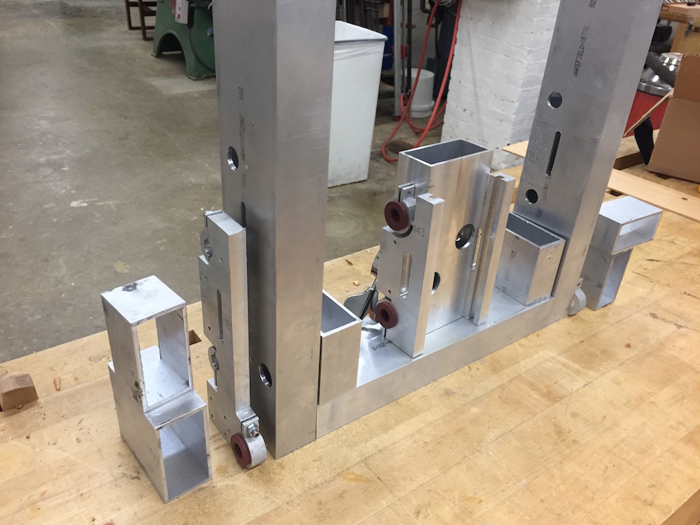
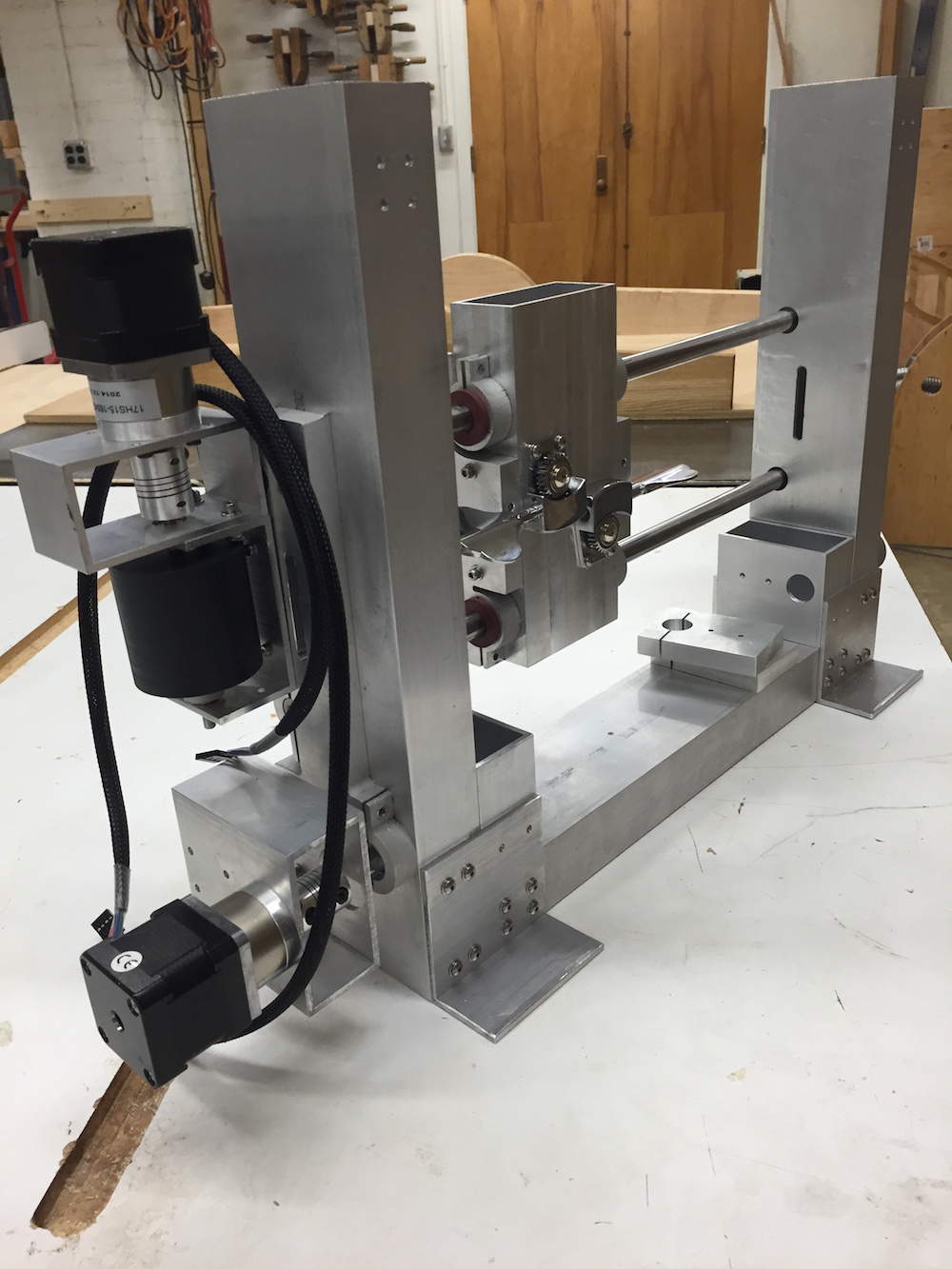
Working quickly to get things fit-tested in the global assembly before our machine expo next Wednesday, I did manage to mount my carriage backwards - oops! I'll have to flip things around and make a few other modifications before presentation day, but here are some pictures of the machine in its current state:
Since I haven't added the access ports for the carriage plate fasteners yet, I had to tighten them up before installing the carriage on the rails. As such, the misaligment preload was plenty enough to make the carriage motion fairly snug. Despite the misalignment, I was able to preserve a reasonably nice motion by removing the bearing clamp screws. While it seems a little tight now, I expect I'll be able to get this sliding motion a little smoother by adjusting the bolts between the carriage plates and tube once I add the access features. Plus, lapping the surface by running the carriage a good number of times will certainly help much in making the bearing interface better.
Future Work (**) - as of 05/08/2016
There are various elements of the machine that still need detailing, since the scope of the project has proved difficult to fit within a single semester. That is, I think I was ambitious to hope finishing a full 3-axis system given the time I had avaliable this past semester, but as it is indeed a project I wish to see thru completion, I opted to proceed with it nonetheless.
Having split my time thinking about the various motion stages, I have marked some elements as due for revisit after I got a basic frame put together. Fabrication has taken longer than I anticipated, so I haven't quite made it to testing yet, but I expect I should be able to start on that front soon.
I hope to address some of these before the machine expo, particularly focusing on the capstan drive elements, but I'll continue working on this project during the summer to get the rest knocked out. Here's a list of elements I've already identified as due for further detailing:
- ◔ Capstan shaft locking
- ◔ X-axis carriage fastener access ports (pins now bolts)
- ◔ Wire rope fittings/ lock onto tuner machines
- ◔ Y-axis part clamping
- ◔ Tailcone live center
- ◔ Z-axis carriage
- ◔ Tool holder
- ◔ Testing and characterization
It's ALIVE!
I managed to knock out the most critical elements listed above as future work. First off, I added access ports for the fasteners on the X-axis carriage. I also secured the capstan onto its shaft. From there on, it was time to revisit the assembly process.
After putting the bulk of the system together, I got the wire rope secured onto one of the tuner machines and fed through the capstan drive afew times before anchoring it to the second tuner. It took some time, and it surely was a matter of patience to keep everything in place until the free end was secured. With the cable drive installed, it was to test it all.
I have further work to do in the next few months, to complete my Z-axis and tool holder. I expect I'll need to take the machine (or parts of it) apart before it's all done, and for this reason, I haven't yet performed the surface precision replication process I have accounted for in my design. Instead, this test assembly has actually granted me the opportunity to prove the value and need for such process! The first time I turned on the X-axis motor, it kept skipping because the friction load on the carriage was too large. As it turns out, the carriage plates were forced out of aligment by the bolts holding them on the tube that makes the body of the carriage. By loosening these bolts slightly, I achieved a clean, smooth motion.
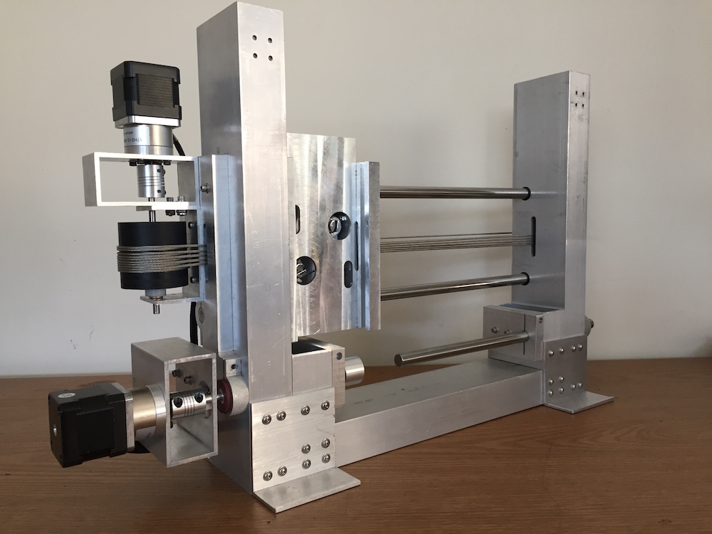
Here are some pictures of the machine in its current state (2-axis):
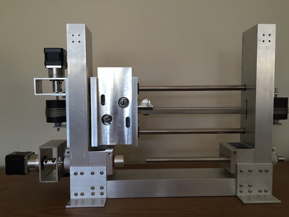
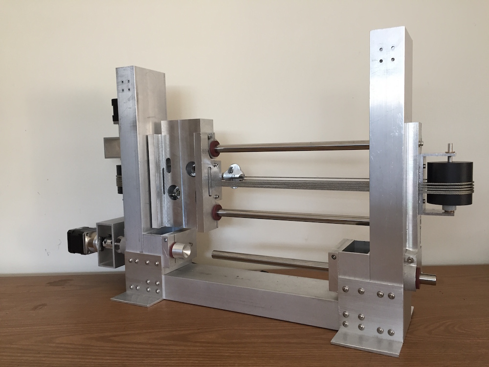
And, of course, a must for a machine of this kind: videos! Here they are:
The machine, moving X and Y:
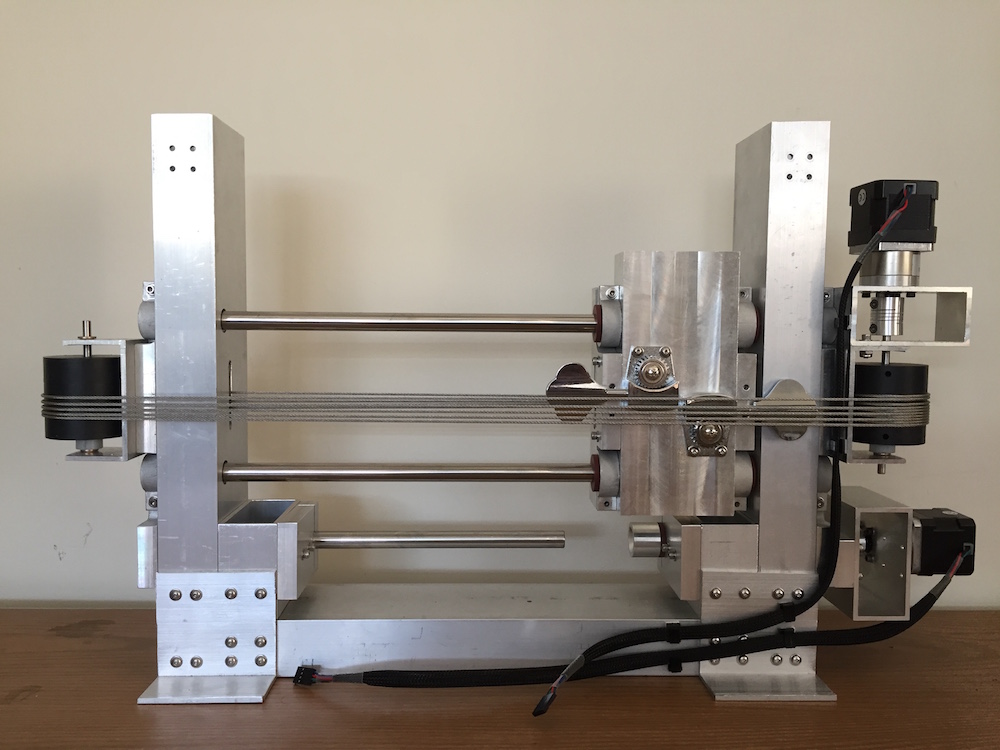
A closer look at the capstan drive:
Here's how the carriage rope clamps manage the crawling of wire rope as seen on the follower pulley: