Part 1 - Initial Development
Parts!
I've been working thru my design and started securing the various materials I still need to put everything together. Since there remain a number of details I need to work out, I might find some extra bits and pieces will be necessary, but I should have a good portion of the stuff I'll be needing. From the actuation end of matters, I've already picked up and tested an extra set of stepper motors.
CAD & Fabrication
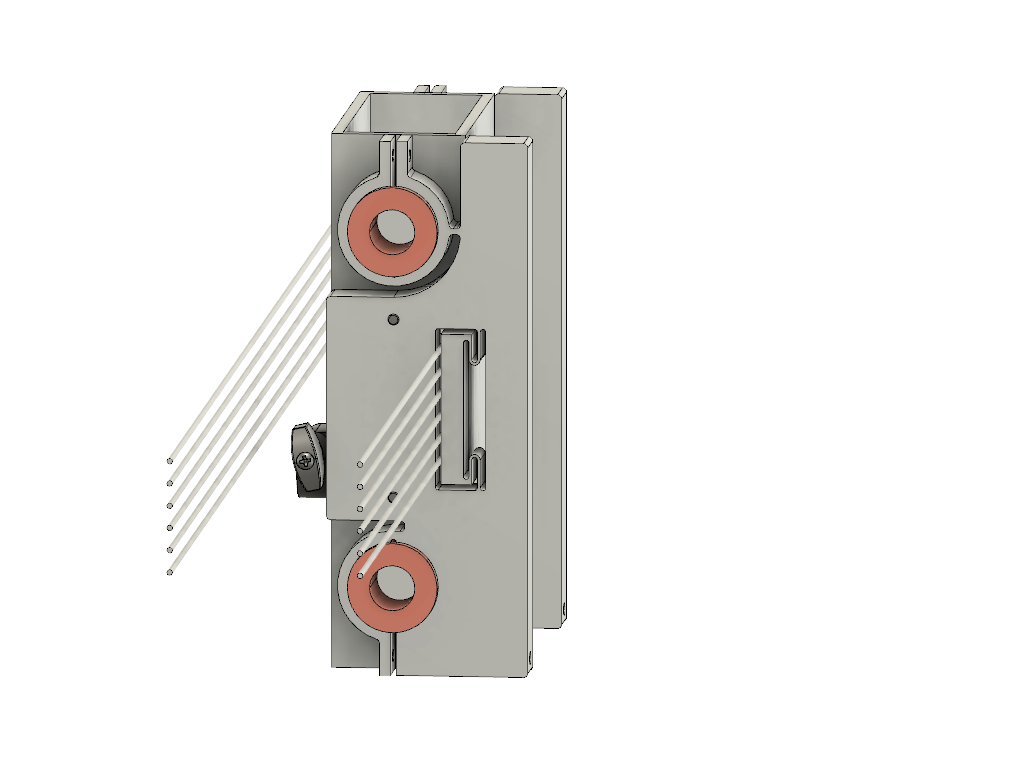
Over the past few days, I made a few improvements to the CAD, including the addition of flexure features on the X-axis carriage. On the top rail bearing clamps, the design provides some compliance to account for possible alignment error between the guides. Near the center of the carriage, the flexures support a clamping feature, to secure to carriage to the drive system.
Part 2 - PREP
Team Review and Feedback
For this round of PREP, we had some very interesting conversations about flexures. Aaron talked about how to use the Freedom, Actuation and Constraint Topologies method - the FACT method - created by Jonathan Hopkins. The FACT chart shows the various degrees of freedom, the desired motions and the different constraints required to achieve the result sought.
We also continued our conversation on belt and cable drive systems, reference features for assembly, and some bench-level experiments. Julian suggested creating a D-shaped pocket with a reference edge, in place of a close-fit slot, to make it easier to align a double-pin assembly. They also suggested I run a few bench-level experiments on the capstan concept, to make sure the line behaves as I expect.
Part 3 - Rework & Updates to Part 1
Bench Level Experiments
I made a few quick-and-dirty mock-ups to test the capstan approach. Just the other day, I was flaking out and coiling my climbing rope, and figured I could try wrapping it around a foam roller. The wider rope made for a good way to illustrate how the line tends to crawl along the capstan. I also ran a few more quick tests once I got the nylon pulleys I intend to use, and wrapping some thread around a pen.
I have run calculations for the minumum amount of travel along the axis of the capstan as the rope wraps around it with the motion of the linear axis. I also accounted for some addtional spacing between the various loops and additional clearance beyond that. The pulleys I got are wide enough to work as capstans, tho the challenge will be to keep the line wraps clean and roughly equally spaced.
On this account, I expect the clamping feature that locks the carriage to the lines may help to hold this spacing. Furthermore, I plan on turning the idler pulley down such that it will hold the spacing between the loops at the follower end of the cable drive.
Parts, Fabrication & More CAD!
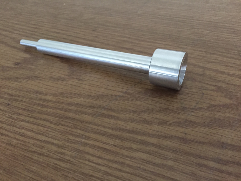
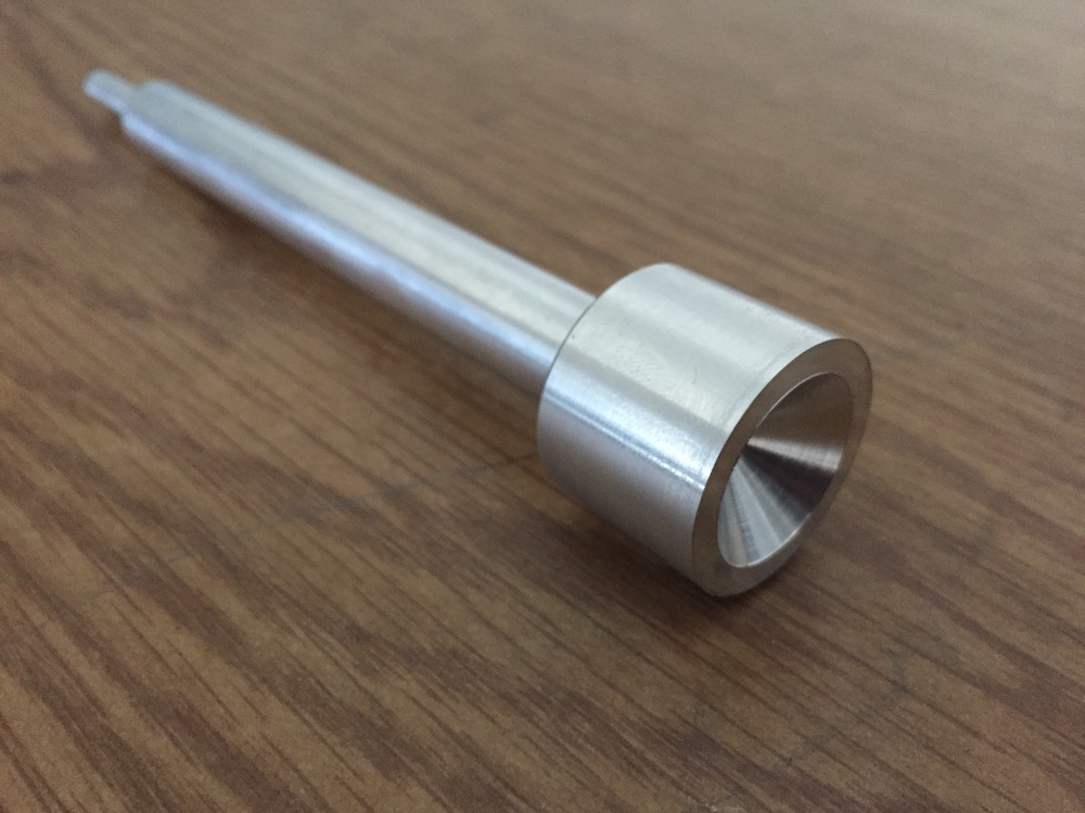
I've been spending time at the machine shop, working on fabrication. While I'm still receiving materials and components I'll need to make some of my parts, I've started off with the structural tubing and spindle shaft. The carriage and risers were cut slightly oversized with the horizontal band saw, and I've started squaring off the faces to make sure I have proper reference surfaces for CNC machining. I've also turned my spindle shaft.
Waterjet - machining dry-runs and design tweaks
After making some adjustments to get the riser and carriage bearing plates ready for the waterjet, I got a cost estimate and decided to start with a dry-run on the laser cutter, to make sure my flexure features were sensible in practice as much as in theory.
Adding to the significant cost of the waterjet cut, this test suggested that I should increase the thickness of some of the features - to err in the side of caution, if I was to see them take form. Alas, I found myself going back to the drawing board for a bit.
I've decided I will preserve the clamping concept on the wire rope slot, but will pursue a different mechanism and do away with that particular flexure. This was, after all, the element that needed thickening of the blades, although it already takes up a significant portion of the plate's face area. Instead, I will machine a pocket and a separate floating block, which may then be held in place with a set of fasteners.
As such, I should be able to make use of the waterjet to produce the compliance feature on the carriage and the rail clamps on the various plates, without becoming prohibitively costly. The pocket will then become an additional step in the post-machining stage, which was already required for these plates in order to add the holes for alignment pins and to bore out the clamp features to the correct diameter.
Beside this setback on my timeline, I still need to work on the design of motor mounts and belt tensioning features, not to mention the Z-axis components. It might take a little longer than I originally anticipated to complete the machine, but I'll keep working on it.
CNC Machining and Waterjet runs
Here's yet another update on the state of fabrication:
I managed to get the riser and carriage plates cut on the waterjet, tho I did have some issues with getting a clean cut thru. I'll have to do a little extra work on post-machining to make sure I get a good reference edge before I add the alignment pin holes and bore out the rail clamps. The flexure feature for the follower rail on the carriage plates seems stiffer than I anticipated, when driving it by hand - but, that's surely a difficult one to gauge in such manner.
I also attempted to finish up the carriage base, tho I ran into an issue while testing the G-code on the mill. It appears the post-processor I had available for the ProtoTRAK wasn't quite compatible as it claimed to be, and failed at some of the transitions in the tool path. I'll have to generate a fresh copy of the program with a different code base. Fo now, tho, I'll have to set this aside since I have an exam coming up. I'll get it sorted out afterwards.