Part 1 - Initial Development
Revisit Concept Details - Error Budget for Structure and Bearings
Having spent the time to become ever more familiarized with the Error Budget spreadsheet, I realized I needed to make a number of updates to my model. To start off, I took a closer look at my bearing stiffness calculations. Since I'm planning on getting Rulon LR sleeve bearings for the linear axis, I reviewed and updated my bearing stiffness spreadsheet based on updated dimensions, such as a more realistic wall thickness, and the corresponding material properties. The latter values I pulled from the following references:
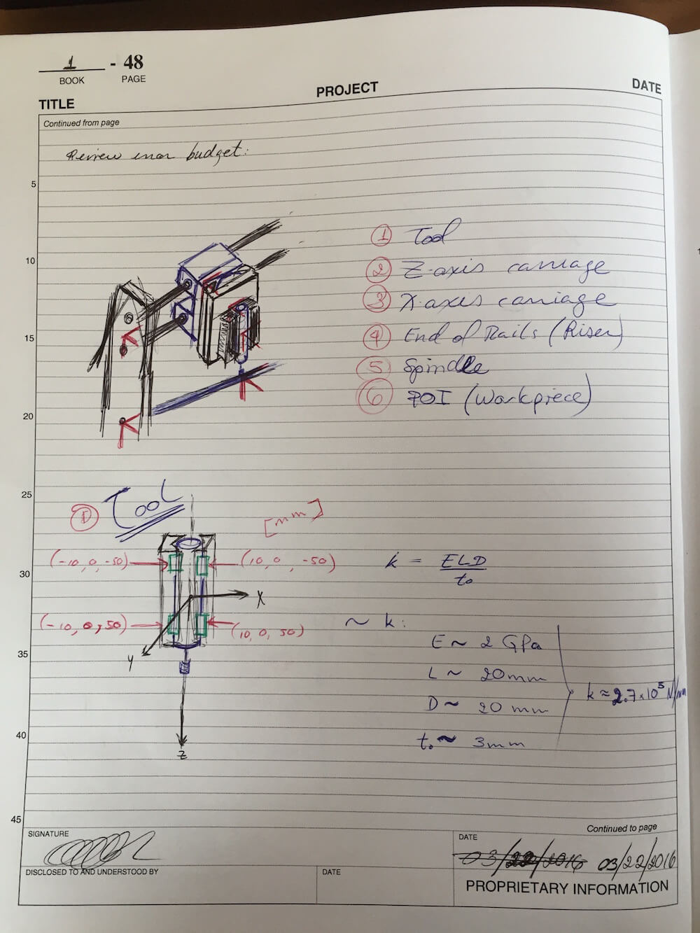
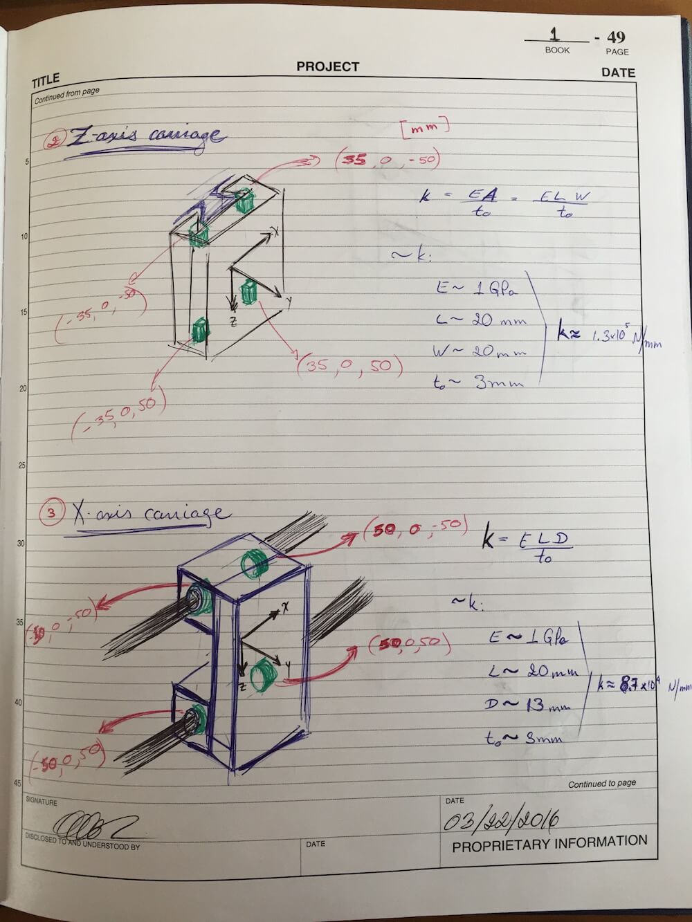
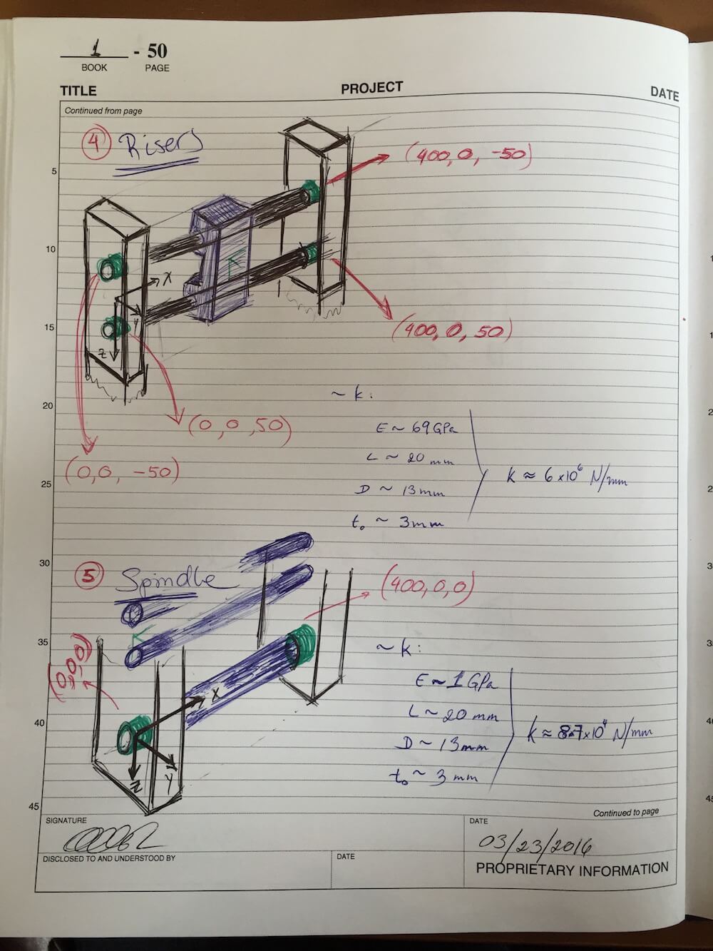
I also revisited my chain of local Coordinate Systems, making adjustments to the location of the origins and bearing or attachment points. Here are the sketches:
These updates, along with some quick component mass estimates, resulted in the following error budget summary:
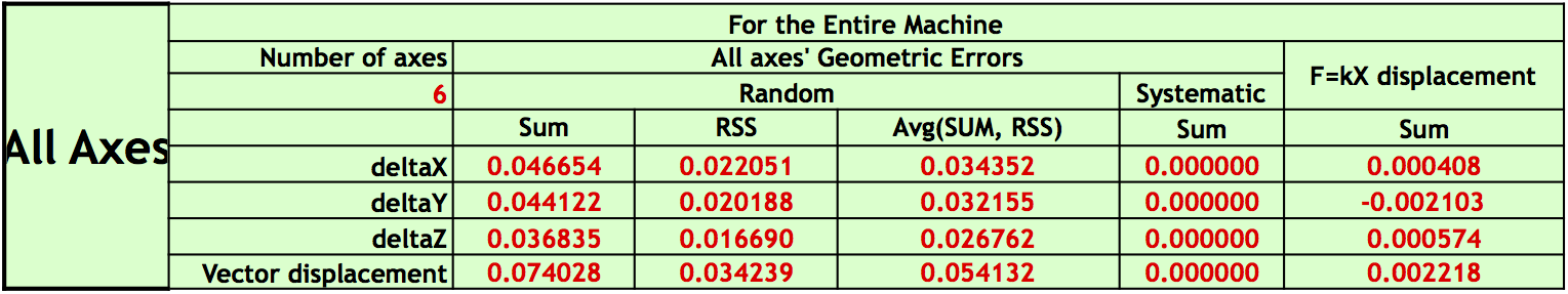
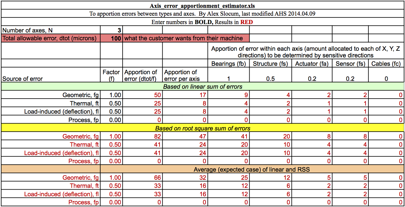
While the values for the geometric errors are only slightly larger than those presented in PUP 6, the load-induced errors appear much more realistic, going from 45 nanometers to slightly over 2 microns. With more reasonable numbers to work with, I took another look at the Error Apportionment table presented in PUP 5 for comparison. This should give me a good idea of how the design is progressing compared to the earlier projections. Here's the table again:
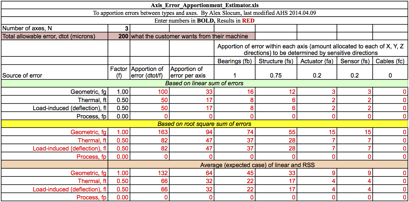
As it stands, the average geometric error for the machine, as shown in the Error Budget summary, is only slightly larger than the allocated error for the bearing configuration on a single axis, and well within the error allowance from the earlier prediction for the entire system. Even when comparing to the tighter tolerances presented in PUP 3 (below), the model falls within the permitted range for geometric errors, if only somewhat limiting the room for error on the other components. Furthermore, the load-induced errors throughout the machine appear to result in a significantly smaller deflection than the allocated value - a full order of magnitude smaller than allocated for a single axis. While there are some effects and loads that may not be fully represented in the model, these comparisons suggest the design process is well on track towards meeting the Functional Requirements.
Now, I should explain what I mean with effects and loads that are not fully represented. Since I have been reviewing my options in terms of drive mechanisms (for the X-axis carriage, in particular), I modeled the system with a stiffness equivalent to that of the bearings in the direction of motion, as opposed to using the actuator stiffness. I've been thinking of using a belt drive for this motion, but there is a risk that the long segments of floating belt will result in too low a stiffness, and too much lost motion due to friction along the rails.
Bearing Life, Linear Stage Friction and Belt Drive Stiffness
With the mass estimates from the Error Budget spreadsheet updates in hand, I proceeded to look at bearing life. I used the pull of gravity on the X-axis carriage and its mounted modules as my preload, and assumed this entire load would be supported by a single rail. This last point stems from the idea that I would want to preload the bearings in a way that used the carriage as a two-force member. Otherwise, it would be difficult to predict which rail would serve as the limiting element (think, reference edge or position master) at any point along the motion. Instead, by using a proper preload and a suitable compliant feature, one rail could be defined as the master, and the other as the follower.
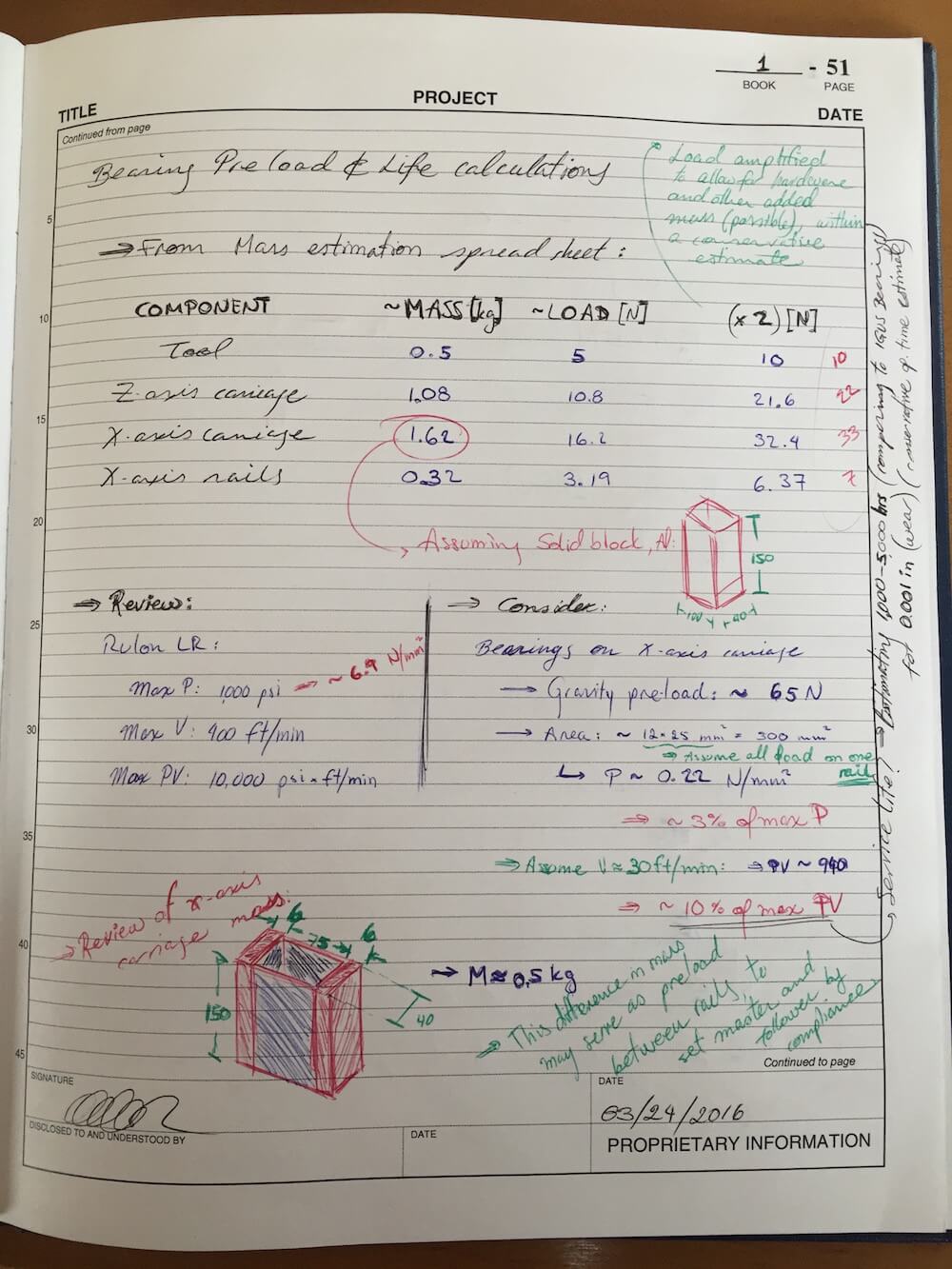
In order to accomodate unknowns such as bolts, tool supports and other hardware, I increased the predicted mass from ballpark part volume by a factor of two, although some estimates were already likely larger than what I expect to end up with since I modeled solid blocks for these calculations. As such, the estimated operating PV for the bearings is in the order of 10% of maximum. Comparing my concept with the life prediction of equivalent IGUS bearings in similar loads conditions suggests that I should expect a service life of about 5,000 hours if I limit the permitted wear to 0.001", and may quite possibly end up with longer life, depending on the exact wear rate. Since the machine is intended for occasional use, this seems like a long enough service span.
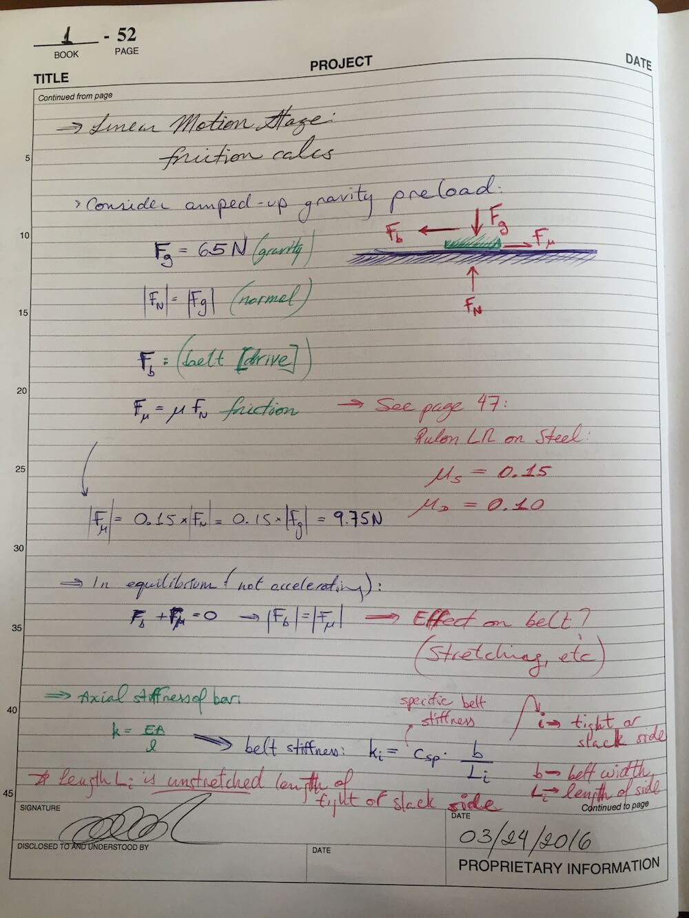
The next point of business, then, was to get an estimate for how much friction may affect the system. Based on the preload and mass estimate from above, I plugged in the coefficient of friction for Rulon on steel, without lubrication - a value of \(\mu_s=0.15\) for the static friction, largest of the two.
It's worh mentioning here that, at the moment, I think I'll be getting steel shafts to serve as rails. They are stronger and cheaper than stainless shafts, tho they will need a bit more attention to keep corrosion away. Since they are meant as linear motion rails, the oil or lubricant may well serve to preserve the steel in good condition and to reduce the effective coefficient of friction.
Next, looking at pure position control (I ignored the cutting force here for the time being), I went on to check the resulting stretch on the beld drive. In an simplified model, as shown in the diagram above, the tension difference on the belt would be equivalent to the friction force opposing the motion of the carriage. Using this value, I went looking for a way to model the stiffness of the belt drive system. I ended up pulling data from the Gates Mectrol catalog:
Now, the belt stiffness can be modeled as follows:
$$k_i = c_{sp} \frac{b}{L_i}$$Where \(k_i\) is the local belt stiffness (tight side or slack side), \(c_{sp}\) is the specific belt stiffness, \(b\) is the belt width, and \(L_i\) is the length of the segment (again, tight or slack). I looked up some potential belt choices, then proceeded to plug in values to estimate the belt elongation due to friction.
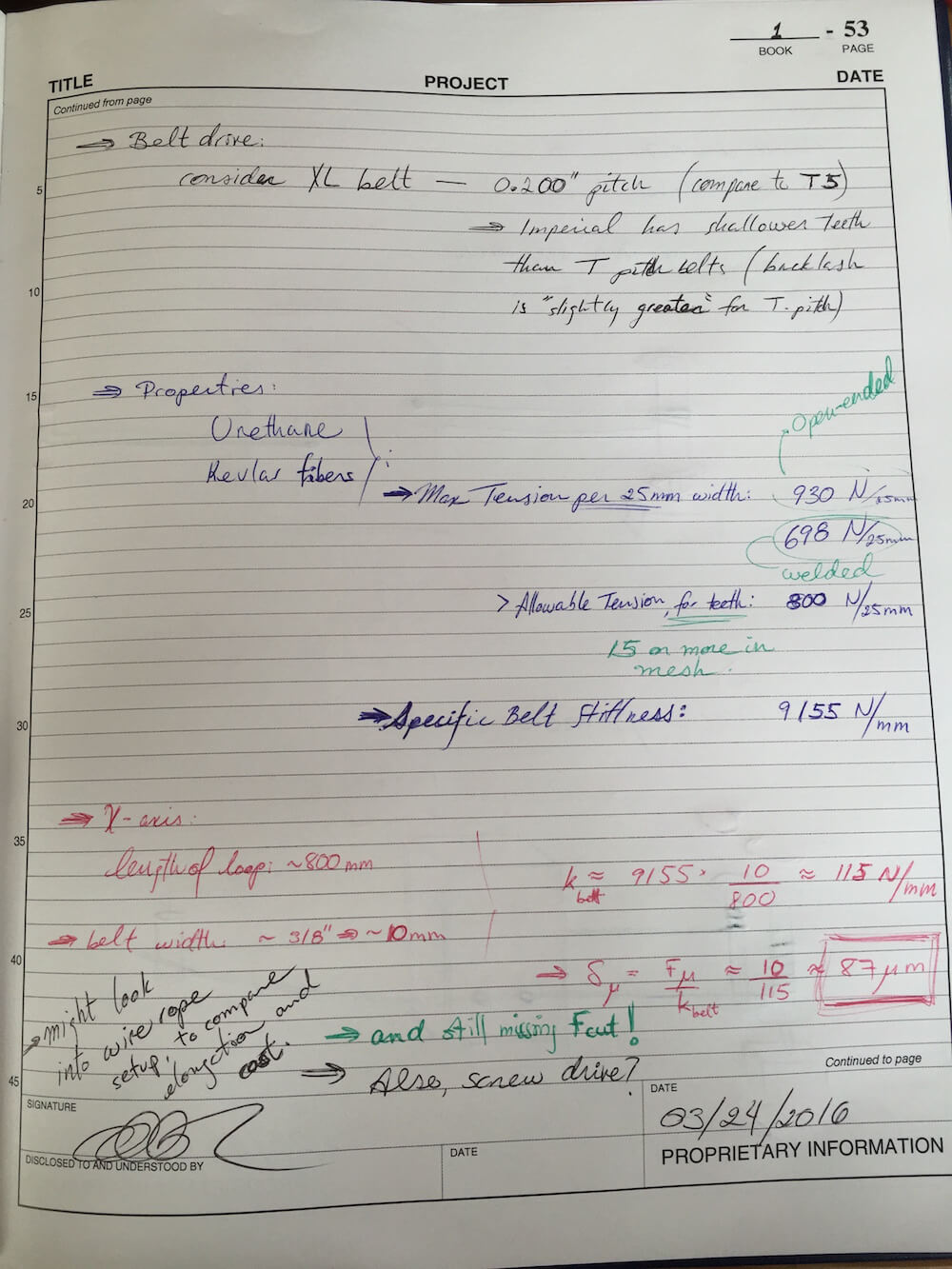
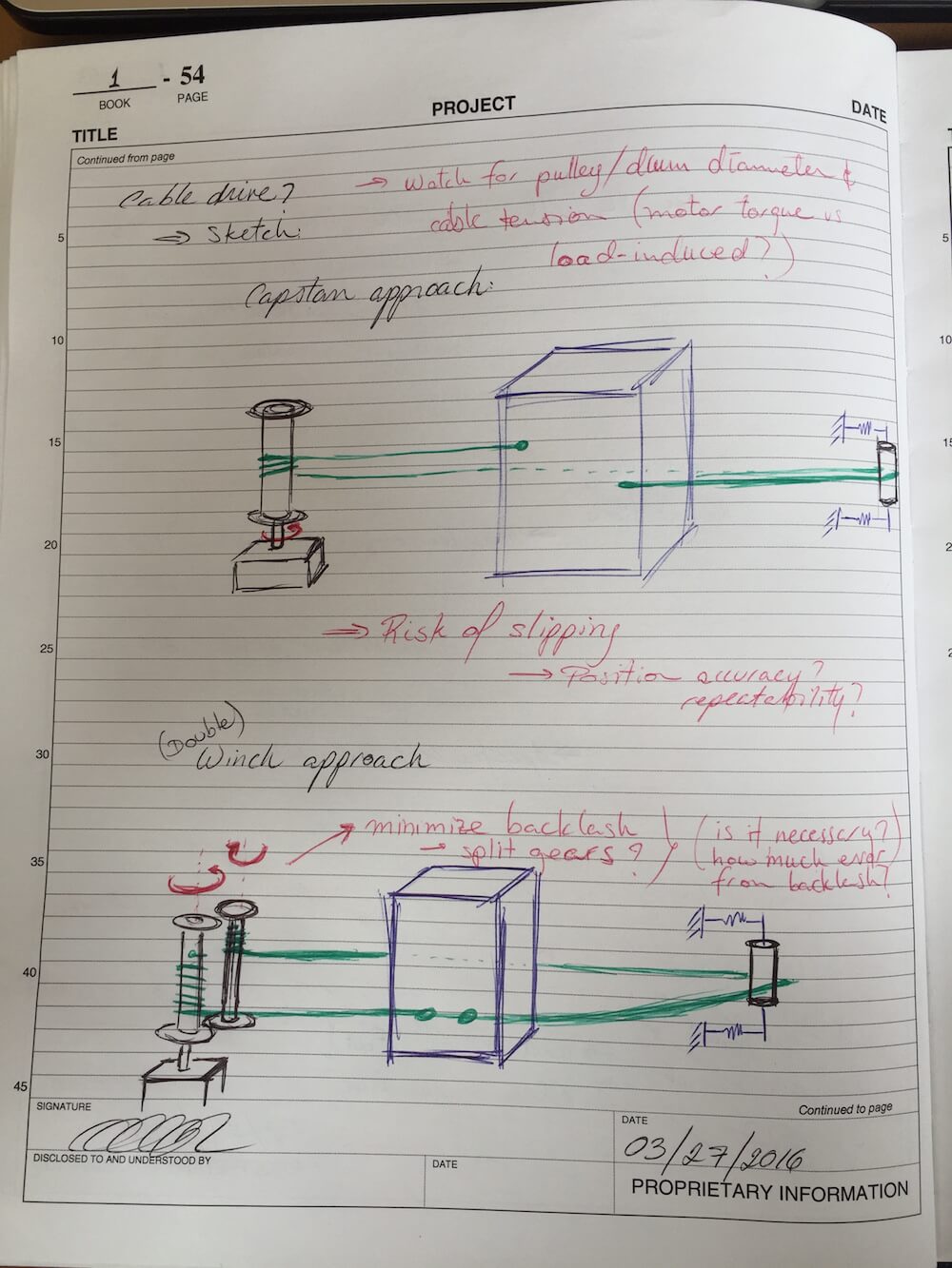
In keeping with the idea of conservative design, I first considered the entire length of the belt as my \(L_i\), netting an estimated 800mm of belt. Assuming a type XL belt of width 3/8" I could order from McMaster, I found that the resulting elongation due to the friction force of 10N would be in the order of 87 microns. While modeling the length of the belt as a single run (the length of the X-axis rails) would double the effective stiffness, the resulting lost motion is still too large for my original error budget. As such, I started looking at other potential suppliers for wider belts I could use. However, in the event that I might not find a belt that fits my application, I went ahead and sketched out some possible solutions to this challenge. Since the issue is that the belt might not be stiff enough, how about replacing it with a stronger tension member? Using wire rope, I could use a capstan drive (which has the risk of slipping just like standard belts) or a double-drum winch system. Here are the quick sketches for these cable drives:
I mentioned earlier that I had ignored the effect of the cutting force for these calculations. Since the cutting force would be about 20N for hard bronze and around 5-10N for wood, I should look into ways of either reinforcing the belt or rethinking the drive mechanism.
Part 2 - PREP
Team Review and Feedback
This time around, we fit three PREP meetings since there were tweaks to our delivery schedule. During the first round, we talked a while about options for low-cost components and standard parts. Aaron and Julian suggested I look into Morse Tapers and other such accessories. I've been keeping an eye out for those.
The second time around, we talked about assembly and alignment approaches. Given the materials I have managed to get, I am working to keep the machining and assembly processes fairly balanced and simple. This might require that I add clearance or compliance for manufacturing, and then finalize the assembly with epoxy or potting compounds to set the components as they are trained into place.
The third time around, we talked some more about the effect of preload on bearing life, and how too much compliance may lead to unwanted noise or even error. Aaron presented a very cool concept to improving the dynamic range of butterfly flexures by anchoring the intermediate stage of a double-flexure (the kind used to effectively cancel parasitic errors) to ground. Aaron also talked about a really cool idea he had been exploring, for a thermal-expansion actuator.
I showed my group the additional calculations I'd performed to check belt and wire rope stiffness, making some adjustments to my area correction factor on the cable based on Julian's feedback - seems like I was being overly consertative with my estimates there. I also went over the sanity check for the belt, where I found the equivalent area coverage of tensile members in the belt would be about 7% for the listed specific stiffness, which we all agreed was a reasonable value.
Part 3 - Rework & Updates to Part 1
Parts, Calcs, Materials & CAD
Over the past few weeks, I've been trying to balance my time between running calculations, looking for parts and potential purchase candidates, placing orders, and developing the CAD model.
Since the belt stiffness calculations didn't turn out as I anticipated, I've had to back-track a bit and rethink some aspects of my assembly. By switching to the capstan drive, I can significantly increase the stiffness of my linear actuator, but the increased pulley diameter means I might have to add a reduction stage. Furthermore, I'll have to rethink my tensioning and clamping features to fit the wire rope.
I've also modified my bearing preload approach based on the feedback I got from Aaron and Julian, opting for a collar clamp instead of a press-fit due to the more forgiving tolerance requirements for manufacturing.
At this point, I have secured structural material - I'll be using aluminum tubing as a base - as well as some belt material and pulleys for the rotary axis and transmission stages, some shafts and the bearings for my linear axis.
As I mentioned, I'm in the process of addressing my linear axis drive mechanism. The image below shows what the model looked like as I started putting my hand sketches together into a solid model. This also shows what it looked like as I started exploring the capstan and cable drive concept:
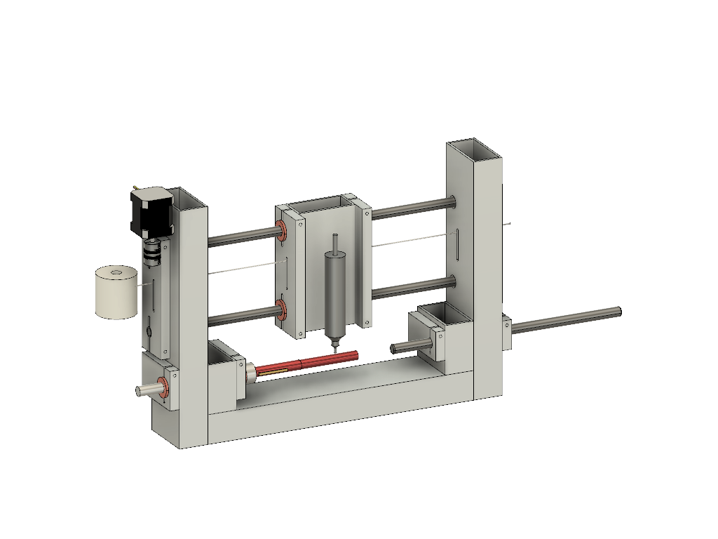
The image above shows the NEMA-17 stepper motor, offset from the capstan for the cable drive. A single segment of 1/16" wire rope is shown across the span of the linear stage. Current calculations suggest that about 6-8 loops will be needed to achieve the desired stiffness. A sample workpiece is also shown, with the live center of the tail support still in the works.
After some more experimenting with the final layout, I actually opted to move the capstan drive to the tail support side. This avoids the risk of catching wires on the spindle drive, and generally gives me some more room to figure out the exact placement of components for the rotary axis of my machine. It also gives me a more consistent visual to keep clear of the tail end support, which slides in and out to accomodate different length workpieces.
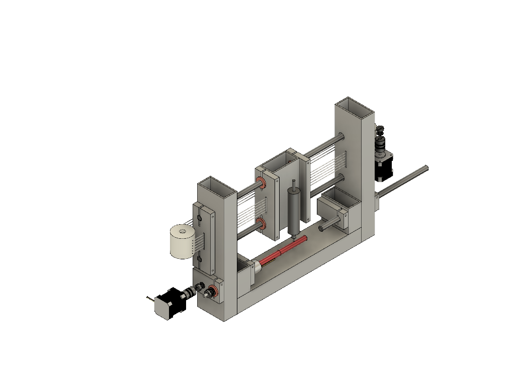
In these renderings, the design principles are reflected thru the length-to-diameter ratios, the use of extension or reinforcement plates to fit sufficiently wide bearings (or bearing surfaces, where appropriate) in accordance with the load capacity and bearing stiffness calculations performed in earlier stages of the process.
I still need to double-check the required pretensioning for my wire rope candidates. I also have to run some calculations to make sure I account for the increased pulley size and resulting motor torque requirement. I also haven't added much detail on the Z-axis of the machine, for tool plunging, at this stage. Since my linear stage carriage also serves as the rail set for the plunger, I'll have to add a reference surface to the block's side plates.