Part 1 - Initial Development
Concept Details - Form Factor, Assembly and Bearings
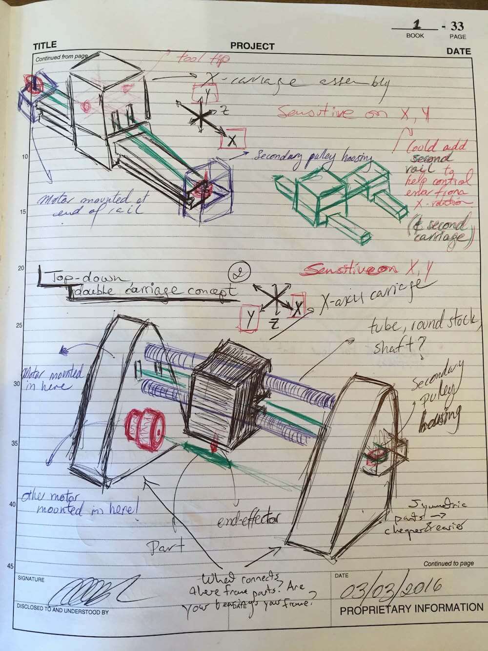
Over the past few days, I've been giving more attention to the details of how I should build my machine - from part manufacturing to assembly and even the user experience during operation or servicing. That is to say, I've been thinking about what parts I could set in place with polymers and adhesives such as epoxy. The catch is, I should only do so for parts I am confident I won't need to take off. It would be quite unfortunate if I put everything together and then decided to make an adjustment on, for example, my tool carriage, only to realize the rails won't come out of the side plates! So, keeping an eye out for the long run as well as the more immediate needs is definitely important.
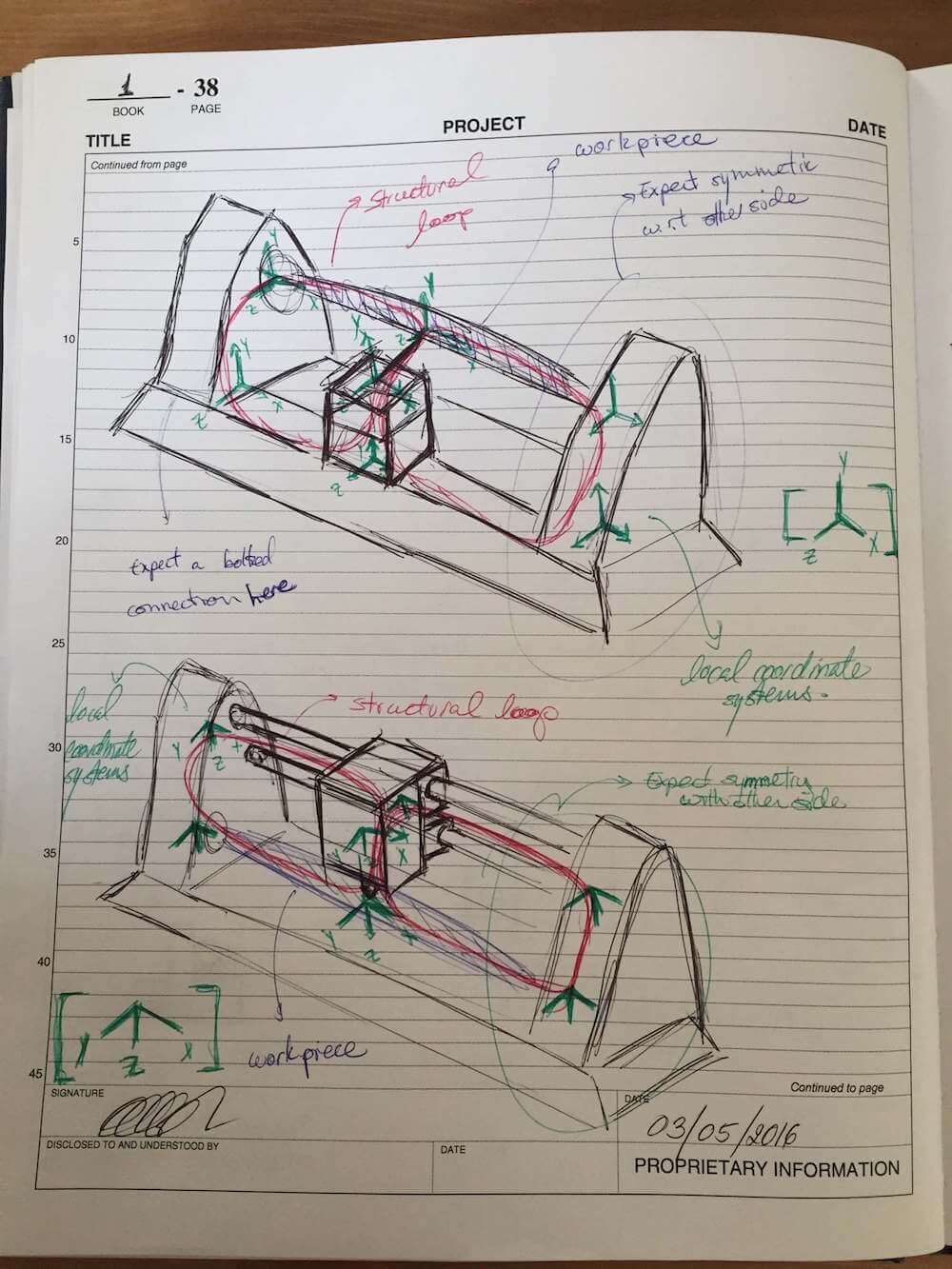
Furthermore, some machine configurations may be able to adjust for misalignments thru error mapping and control software adjustments. Think for for a moment about a planar 2-axis system - a mill, for example. If the X and Y axes of motion aren't perfectly orthogonal in the final product, this can be adjusted by operating both motors in synchrony to make up for the error. In other machines, however, there are limitations to this type of correction due to the nature of the system's geometry. Such is the case with my design, where it is necessary to ensure good alignment between the workpiece axis and both of the rails that support the linear motion stage that translates parallel to the workpiece.
With these risks in mind, and following some advice from last week's peer review, I added a few sketches to my design notebook to illustrate a few possibilities for mounting the rails and carriage.

Besides using a CNC program for machining, also taking advantage of a setup that would let me machine both sideplates together would help ensure good alignment between the reference features on them. Then, by making sure I run the machining operations for the linear axis shaft mounts and the rotary axis spindle mount at the same time, I would get the closest alignment between these parts. I just have to make sure I add appropriate compliant features where they may be needed.
Error Budget
Next up, time to take a closer look at that error budget. Bearing stiffness, random error motions and the structural properties of the machine all have their place in the resulting performance of the machine, and it's most definitely something to look at from an analytical perspective before calling the design good and even thinking of moving to detailed CAD or manufacturing. For that purpose, the first step is to break down the structure into more manageable elements, by placing reference coordinate systems at the critical nodes along the machine.
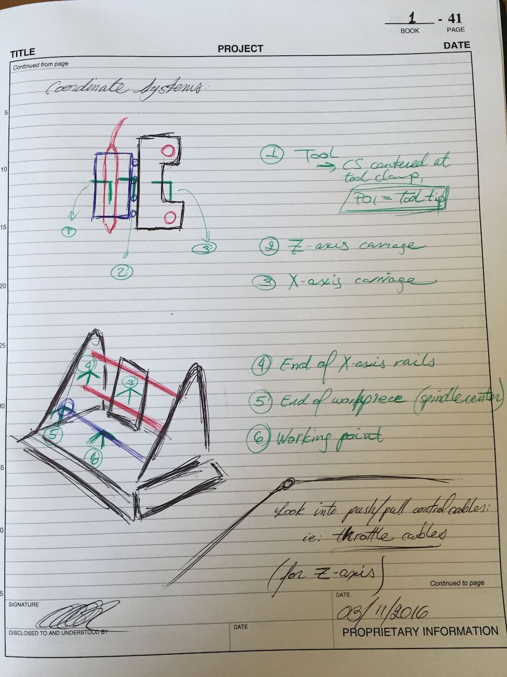
This illustration presents the local coordinate systems used as reference to implement the Homogeneous Transformation Matrix approach which facilitates solving for the machine's deformations due to random error motions as well as machine stiffness versus applied loads. Note that the image above builds upon the references presented previously in PUP 5 - for the sake of clarity, consider these images from last week's archive:
Of these, the first highlights the sensitive directions of the machine, boxed in red on the global coordinate system. The second image shows the various nodes used as origins for the local coordinate systems used as part of the error budget analysis.
Part 2 - PREP
Team Review and Feedback
This week, my peer review group focused on building a better understanding of the error budget spreadsheet we have been provided as part of the course resources. We talked about how it relates to the various concepts we have been discussing in lecture, and how it may apply to our various machines. The reason for this, in part, stems from the fact that there is so much going on in the spreadsheet.
Even after going over the fundamental concepts behind this tool in lecture, it took some time to trace back the various formulas and principles on error analysis we had learned about. For example, Julian asked how load-induced and purely geometrical errors were combined. We spent some time reviewing the notes from Precision Machine Design on this matter, and following the dependencies from the summary view on the spreadsheet. As we moved thru the various tables, we got a much better grasp on the tool's underlying philosophy and layout.
An example of this, building on Julian's question, was that we concluded the various types of error are actually kept separate throughout. The axis definition tables serve as a space to enter all manner of parameters for a given coordinate system - its structure, bearings and random displacements. The Coordinate Systems and Loads table, as we had discussed during lecture time, provides the relative positions of all local coordinate systems, and any loads applied - this could include operational external forces, weight of the structure, and any other inputs a designer might want to consider. The Summary tab, then, brings together all these parameters: it uses the local origins and machine geometry as a reference to estimate the equivalent error due to random motion, and the various compliance matrices and forces to account for the load-induced error. These results are then presented side-by-side at the top of the Summary table.
Part 3 - Rework & Updates to Part 1
Bearing and Structural Stiffnesses
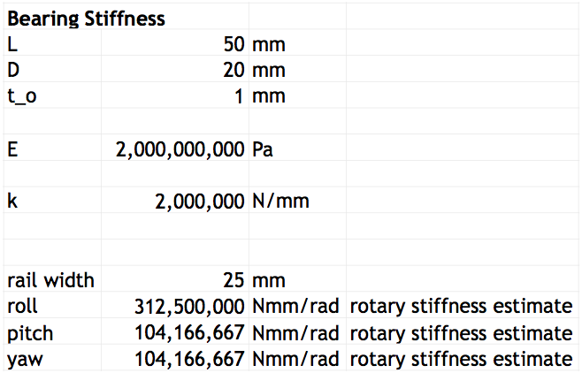
After the PREP meeting, I pulled my notes and started looking at the bearing stiffness and structural compliance matrix sections of the error budget spreadsheet. Since I'm considering sleeve bearings for the X-axis carriage, I started off with the following equations:
$$ \sigma = \frac{F}{A} $$ $$ E = \frac{\sigma}{\epsilon} = \frac{\frac{F}{A}}{\frac{\Delta t}{t_o}} $$ $$ E = \frac{F t_o}{A \Delta t} $$ $$ F = kx = \frac{E A}{t_o} \Delta t $$ $$ k = \frac{E A}{t_o} = \frac{E L D}{t_o} $$Where \(E\) is the modulus of elasticity, \(L\) is the sleeve bearing's length, \(D\) is its diameter (to approximate the sleeve as a flat bearing), and \(t_o\) is its wall thickness. For a first approximation, I made a few guesses to the dimensions and material of the bearings, and obtained the following:
I also considered a few models for the structural components, and built a spreadsheet to find the corresponding compliance matrix. Here's an example:
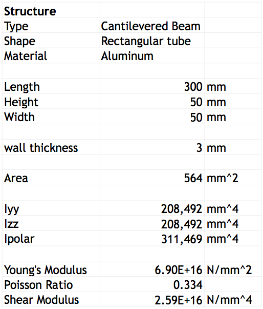
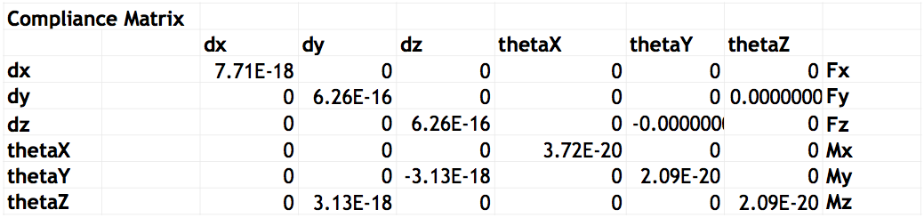
I then used these compliance matrices as inputs for the different axes in the error budget spreadsheet. Among the things to note, however, I must start with the following remark: while my design is more like a bridge machine, and would be best modeled as a simply supported beam, my current spreadsheet models it still as an open-loop structure - a series of cantilevered beams. Furthermore, I still need to setup the compliance matrices for some elements of the machine, which I am currently modeling as square tube sections.
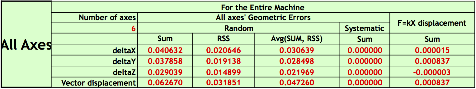
As I looked thru the results, I noticed one of my local systems was contributing a significant majority of error, a full 2 orders of magnitude larger that the next. Since I am modeling the system as cantilevered beams, I figured this might be an artifact of how I interpreted the associated bearing placements. I went back and moved the origin of this problem axis to be centered between its supports, and the error estimations came to a more even distribution among all elements. Here's what I'm currently getting for the overall summary:
While this first estimate looks promising, it is certainly missing a more detailed consideration of the bearings and members. I'll need to update the various section profiles to more accurately reflect what I have envisioned for the structure. Once I get the updated compliance matrices and bearing stiffnesses, I should be able to move forward with these results. I also need to add estimated structure weights, and an estimated friction load for the actuated axes, to get a more reliable load-induced error prediction.
For bearing life and preload, I've started by looking at some potential candidate materials and dimensions. As it currently stands, I expect to be getting a minimum dynamic load capacity of 150lb @ 50rpm based on sample McMaster-Carr parts, tho I might be able to get better performance depending on the choice of bearing, and of shaft diameter. If I consider the estimated weight of my machine from the early structural loop models, in the order of 30kg, these bearings would be able to handle the load well enough. As for the listed speed, 50rpm on a 1/2" shaft is equivalent to about 6ft/min, which might be somewhat slow as a limiting factor on my machine - this warrants a closer look at the bearing life ratings to ensure the final load and speed conditions are within capacity. For reference, if I opted to get PTFE-lined bronze bushings, the load capacity would go up to 7,000lb @ 25rpm. Regarding preload mechanisms, the sketches in Part 1 show ideas such as a tapered beam fitting, a radial clamp and a dual-V-groove configuration. These will exhibit different contact stresses, so I should keep this in mind and revisit my calculations to double-check the chosen approach as I move forward.
Risks and Countermeasures
In Part 1, I mentioned some of the risks and countermeasures I've considered. To recap, the main concern is with alignment of the side-plate features, so I plan to machine these using a CNC program and, if possible, machine both plates at the same time, so the hole pattern will be as close as possible.
In terms of assembly and servicing, I will opt for elements and features that will allow me to take the machine apart if needed. As such, I'll try to avoid using epoxy or other adhesives on the rails. Instead, I will focus on providing a suitable reference surface and adjustable-preload clamping mechanism.
As was the case with PUP 3, we were given the opportunity to revisit our work for this week after further discussing the relevant material during lecture. These additions also touches on the I had presented above as needing review.
Revisiting the Error Budget Spreadsheet
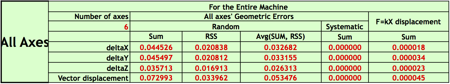
For this follow-up, I started with getting a very rough estimate for the mass of the various components along the structural loop based on ballparked volume. I then doubled this value to accomodate for unaccounted hardware and geometric modifications, and added them to the chain of local coordinate systems. I also evaluated the effect of adding a vertical reaction force at the node most closely connected to base of the machine, since my coordinate systems are grounded at the active point on the workpiece.
Other modifications involved adding more detail to the compliance matrix models. This included exploring more closely the effect of different cross-sections, as I spent some time exploring options for shafts or tubes to use as rails, and the potential cost of the respective bearings to match the different diameters. I've considered MDS-filled nylon and Rulon as good material candidates, with preference towards the latter so long as it remains within budget.
I also made corrections to the stiffness model of the double-rail configuration, accounting for the adjusted torsional compliance and the simply supported arrangement.
For bearing rails and motion axes, I have estimated a random error motion of about 5 microns. In the case of coordinate systems centered at structural joints, such as the attachment of the rails (in principle, a fixed connection), I have input 1 micron for such errors, intending to accomodate possible minor displacements due to vibration during the operating life of the machine.
I did notice that if I entered a value of \(10^{-6}\)mm for the rails, my geometric error predictions became extremely large, and for values in the order of \(10^{-10}\)mm it settled to a similar range as with 1 micron, which suggests I should proceed cautiously until I have a chance to retrace this issue and identify the source of this behaviour.