Part 1 - Initial Development
Reviewing Cutting Forces
Before getting into detailed concept exploration, I needed to review my cutting forces. At the end of PUP 3, I mentioned the original estimate might not properly reflect the loads for engraving, which is the primary purpose of this machine. I wanted to make sure that my early estimations made sense before I started thinking about bearings and rails and all that good stuff, since I have a limited budget for purchased parts. Odds are I won't find all the perfect components in the scrap piles at the shop, and I should have a good idea of what allowances I can get away with, or if I should be more lenient on my accuracy requirements.
With that in mind, I asked Aaron (he specializes on cutting processes) for some suggestions on sources and went looking for cutting force and power equations I could use, to compare with my original numbers. After some browsing around, I pulled this equation from Machinery's Handbook:
$$P_c = K_p C Q W$$Here, \(P_c\) is the cutting power, \(K_p\) is the power constant, \(C\) is the feed factor for power constant, \(Q\) is the material removal rate, and \(W\) is the tool wear factor. In turn, the material removal rate for milling processes is calculated from the feed rate \(f_m\), depth of cut \(d\) and width of cut \(w\).
$$Q = \frac{f_m w d}{60,000}$$Looking thru the various scaling factor values, I opted to work with the simplified version of the equation for a first order estimation:
$$P_c = K_p Q$$The power constant \(K_p\) tells about the power required to remove a unit volume of material. As given in the reference tables in Machinery's Handbook, using the metric system, this parameter has units of kilowatts per cubic centimeter. As for the geometric parameters, I used the following approximations:
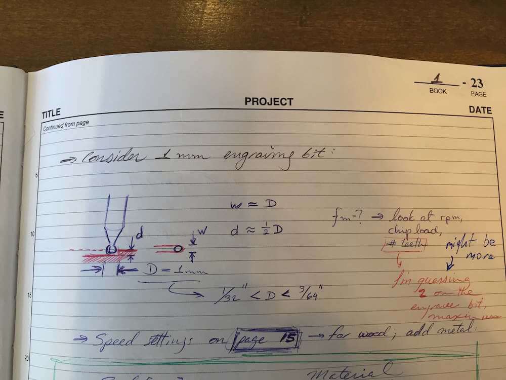
Using this approach, I found that the cutting power should be as much as 26W for engraving hard bronze, and closer to 10W for soft metals and wood. I plugged these power values into my cutting force spreadsheet, and found that the respective force would be in the order of 20N for hard bronze, or about 10N for soft metal and wood.
Concept Development
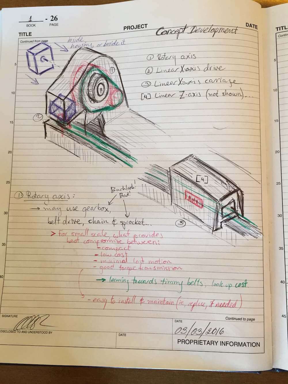
Next up, time to make some sketches! I'm going with the horizontal X-axis strategy, so the machine will probably look a little like a miniature lathe. The way it operates is probably more reminiscent of a mill, tho. In any case, I have a few ideas to explore. In particular, I'll focus on the X-axis linear motion, since it is responsible for the longest displacement among my machine's different motions.
For example, I could make my X-axis a ground-supported linear guide system:
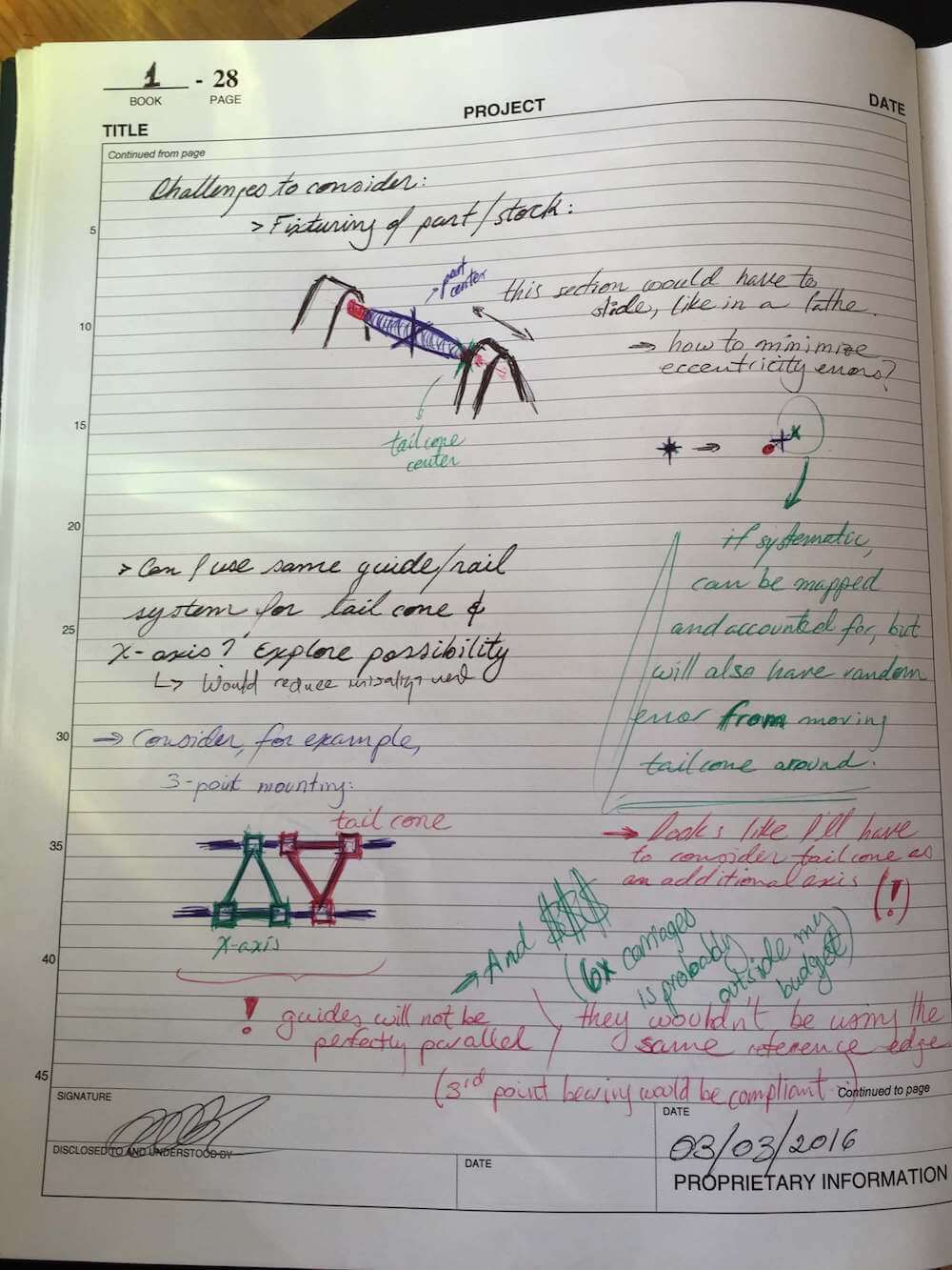
Since a single bearing block carriage combo might not be enough, I could look into using 3 blocks for the X-axis carriage (and perhaps even mount the tail cone on that as well!):
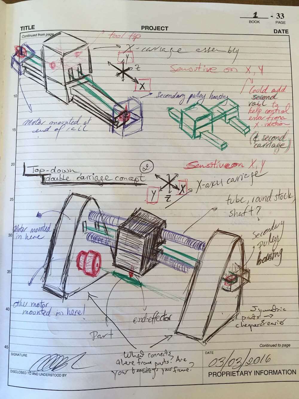
I could also try using round shafts instead of fancy rails:
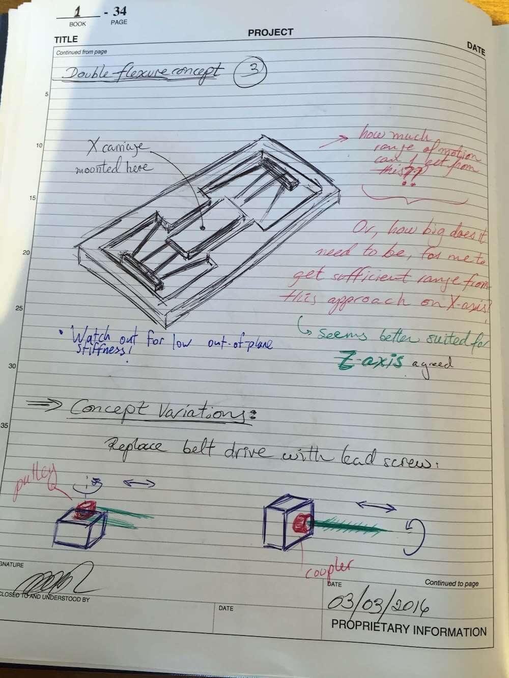
Or, I could look into building a flexure bearing for the carriage:
Here's a closer look at my machine's sensitive directions:
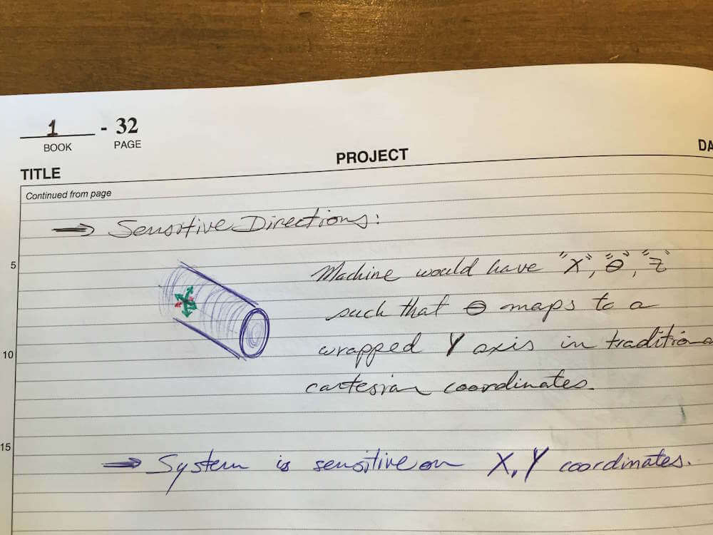
I'm not terribly concerned with depth control. While I have to keep an eye on it and make sure I don't overload my system, I can build some compliance on it if necessary. My main concern is in having a good position control for the other two dimensions, since my intent is to transfer a drawing onto the part. Think of it as a wrapped plane, instead of a flat piece of paper. If I can get reasonably consistent depth in the traces, that's so much the better. At its worst, the machine would still allow me to use the traced features as pockets to fill with inlay polymer materials - which is, in fact, one of the first things I want to try with the machine!
Here are some of my concerns with these ideas:
- Dust
- Particularly for the first concept, with the ground-supported bearing rails, I am worried that the system will accumulate too much dust from both the environment and its own operation, to the point where it might hinder the X-axis carriage motion. I could install a shield to cover the rails, or look at the second concept, where the rails are above the workspace and are less likely to collect dust from it.
- Rail or shaft misalignment
- This is an issue that affects both carriage binding and misalignment with respect to the workpiece. I could design the machine to allow adjustment of the rails during assembly, to ensure a smooth motion. I could also build some compliance on the slave/follower bearing block.
- Drive System
- I've focused on two possible drive systems for my X-axis: a timing belt drive, or a lead screw. Both of these present challenges of their own, and should be weighted against the rest of the machine. The belt drive might be too compliant and thus less accurate for position control, while the lead screw might lead to binding due to misalignment. For the belt, I should pay extra attention to the numbers on stiffness, and how my system's error budget may be affected. For the screw, I could look into building some compliance on the tracker nut.
Part 2 - PREP
Team Review and Feedback
In reviewing my updated cutting force calculations, Aaron mentioned I might have been too conservative, since I first ran numbers for cutting metal instead of wood. Julian agreed that in so doing, I might be over-designing. However, I am interested in keeping the feature - I would like to use the engraver on brass as well - if I can fit it within my budget. The only way to know if it would be possible was to run these calculations. Since the computed forces are lower than my original estimations, I think I'll keep it that way for now.
Aaron also commented on my choice of speed settings for the power calculations. My logic was to use the recommended speed settings and chip load per tooth as a baseline to find the feed rate, since these would give me the largest material removal rate and power values. I could always drop the speed on the tool. Then again, Aaron's note makes me wonder if I could actually use the higher speed as a feature - could I (intentionally) burn wood with it, too!?
I wanted to get some feedback on possible approaches to the over-constrained carriage issue, so I asked my peers for their thoughts on some ideas. They provided some good pointers on the pros and cons of polymers like epoxy - how they can be set into position during assembly, giving some helpful flexibility during the machining phase, but might make it difficult to take the thing apart in the future. Julian's suggestion of the bolted connection for the slave rail was also interesting.
I also got some good pointers to brands and sources of bearings and components to look at as I decide what to buy and what to build for my machine. Some of the more well-known sources are often overpriced in part for the convenience they provide, so knowing about other places to look can save me some money.
Part 3 - Rework & Updates to Part 1
Revisit Error Apportionment
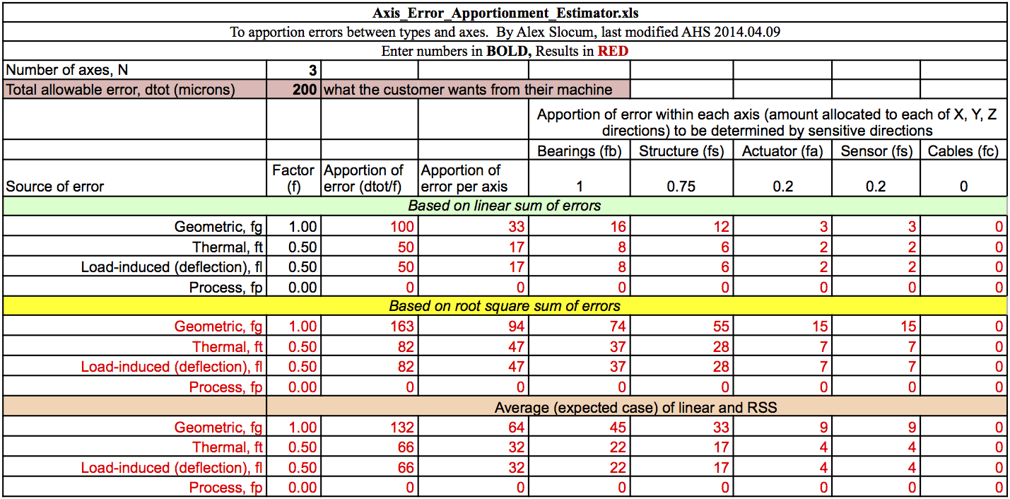
I've revisited the error apportionment from PUP 3. In this version, I have softened my accuracy requirements, for two reasons. The first one is, in looking at my application versus the resources available, I expect to be more limited by the latter. My application doesn't require extreme precision, since the intent is aesthetic in nature. As long as the machine is able to trace a good-looking mark on the workpiece, it is enough. For this, I am considering the width of a pencil lead - typically around 0.7mm - and a line overlap of about 50% as a reference for what would be good enough.
Furthermore, the error apportionment table accounts for all motions, without necessarily accounting for sensitive directions. Since my concern is mostly on the wrapped surface plane, I expect the results will be sufficient when I design with what I consider the maximum acceptable in-plane error as my total system error. That is, part of the spacial displacement should fall onto the non-sensitive direction, giving me a perfectly acceptable trace on the workpiece.
I have also changed the factor for structural error allowance. I'm expecting the assembly process will play a critical role on this matter, and may prove a source of significant error when I try to align two slide rails and the workpiece axis. Here's what I have come up with for this stage:
Further Exploration
I'll be focusing on the first and second concepts presented above, with the global coordinate systems shown in the respective sketches. Here are the FRDPARRC tables:
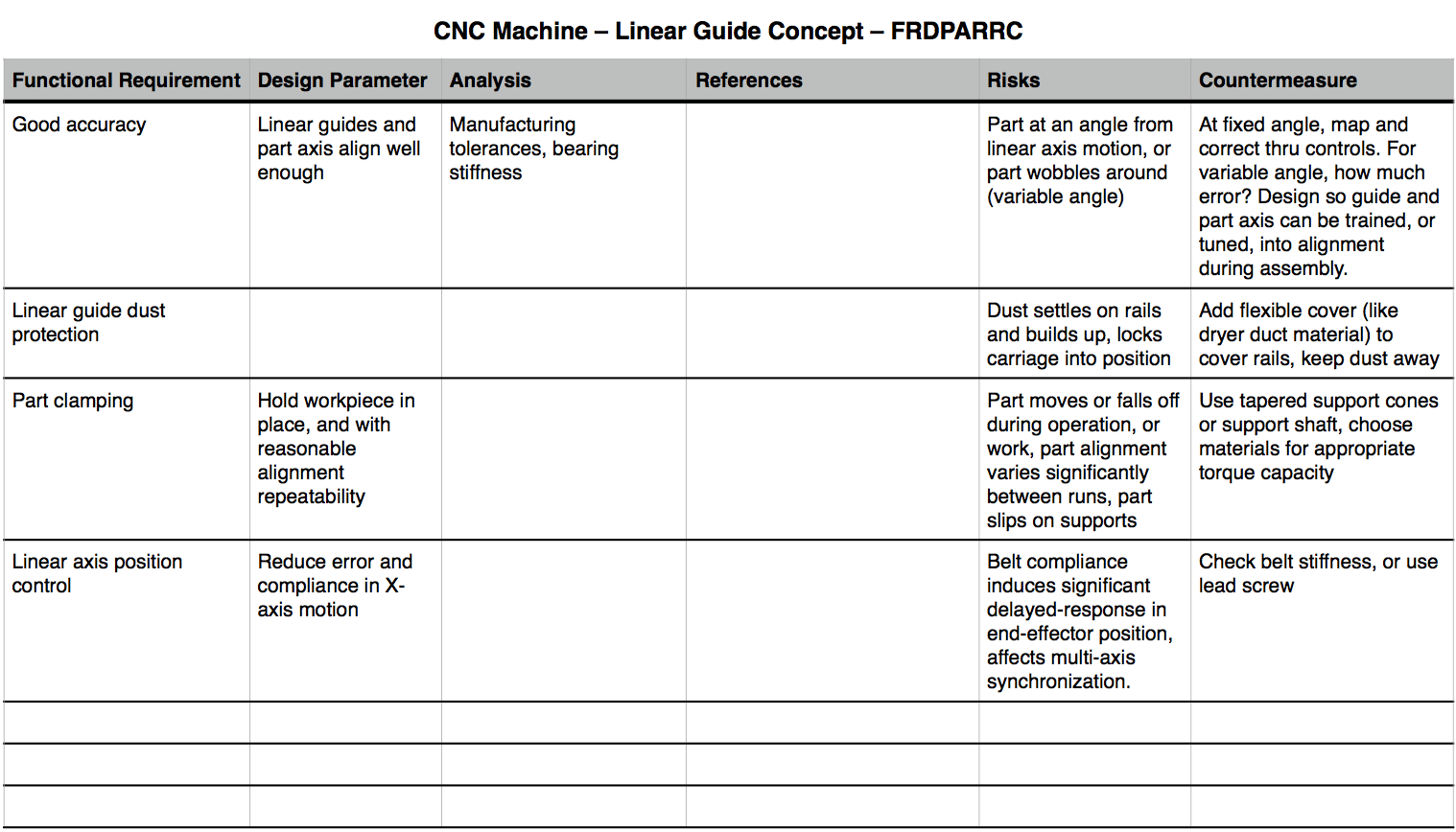
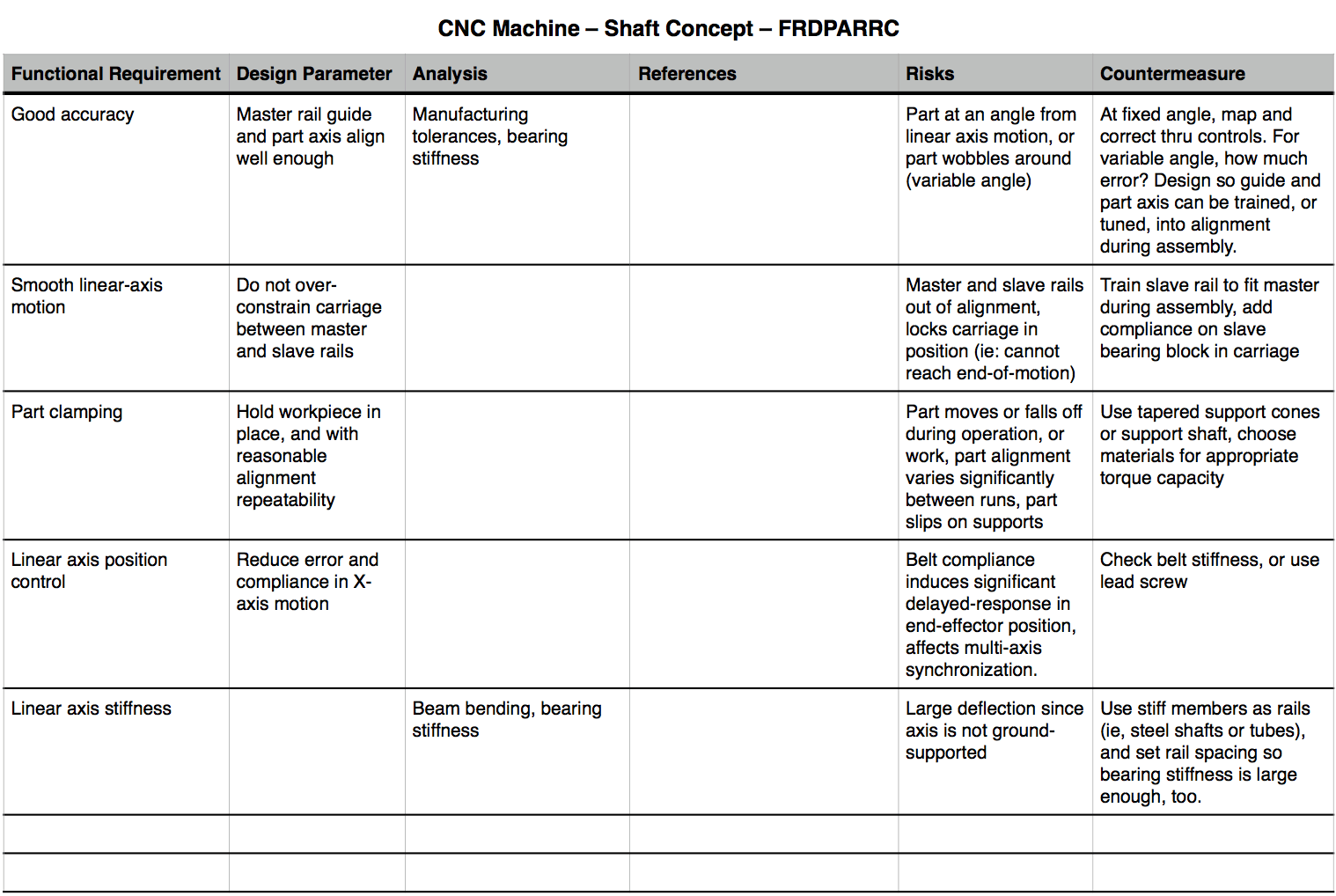
Here's a sketch for each concept, with the various local coordinate systems marked up for error analysis:
First Order Error Budget
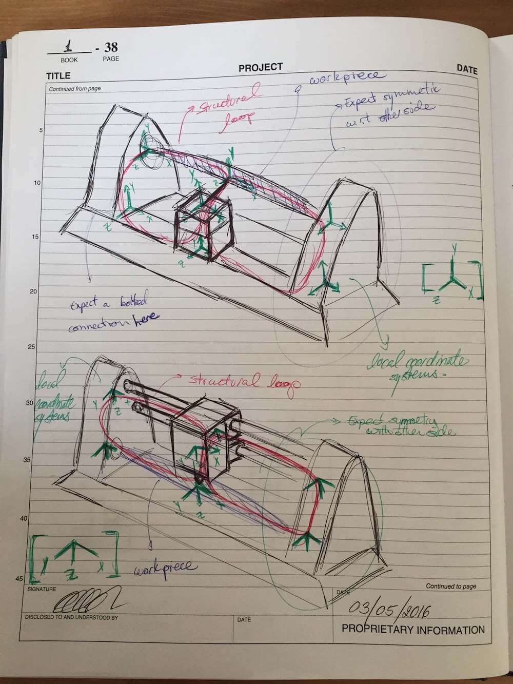
As a first order approximation, I should be able to start off using the geometric error gain table from PUP 3. Just to double-check that they still apply:
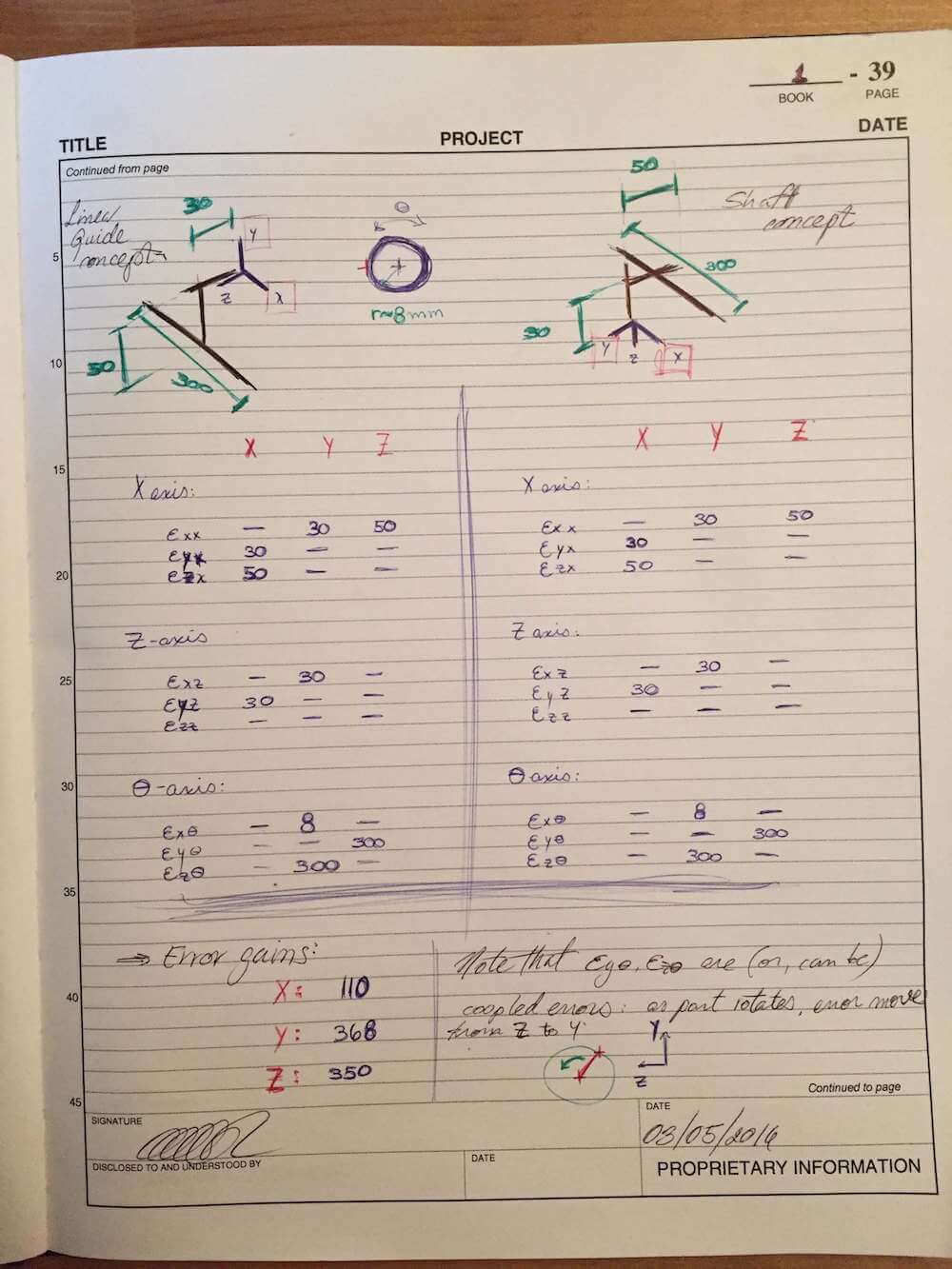
While my initial geometric error gain review assumed the part and the X-axis were well aligned, I have added the off-axis rotations of the workpiece (Theta-axis) here to remark how critical proper alignment will be for this machine. As long as I can get these true to one another, the next most critical motions come from the X-axis carriage. Since these largest error sources relate to the relative position to the X-axis, that's where I should focus my efforts and my error budget - the concentric clamping mechanism, plus the structure and bearings for the X-axis. I think in that regard, my latest version of the error apportionment table should be good for now.
Since my top concepts seem to be doing rather alike in terms of error gains, I'm currently leaning towards the overhead shaft-slide concept for its likely reduced dust collection. I'll have to take a closer look at local stiffness requirements next.
Risks and Countermeasures
I think both concepts give me a fairly accessible platform to work with. Things that I should start looking into, tho, include the addition of limit switches to prevent bottoming out and overloading the motors. I could also consider adding bumpers or shocks at the end of motion on the shafts. And I might still need the 3-point steady rest, or a follower rest, to help support the workpiece. Perhaps an adjustable (or spring-loaded?) block with a V-groove could help with both alignment and support of the part, as long as it's made of some low-friction material.