Part 1 - Initial Development
A Little Background
If you've made your way here after looking thru the previous Problem Sets, you've already seen my brief introduction to exact constraint systems in PUP 2. The planar device presented a few weeks back illustrated this concept for a body limited to planar motion. However, the world is certainly more complex than that. This week, we expand on the idea of exact constraint for rigid bodies in free space. Coming to theaters near you, now in 3D!
Just to recap, a rigid body in 3-dimensional free space has 6 Degrees of Freedom (DOFs):
- 3 Translations:
- Along the X axis
- Along the Y axis
- Along the Z axis
- 3 Rotations:
- About the X axis
- About the Y axis
- About the Z axis
Thru PUP 2, I started off with the example of a bead on a string, as an illustration for a one-dimensional system. With only one DOF (the translation along the string), a single point of contact is enough to fully define the system. Then, for a 2-dimensional system, we have to account for the 3 DOFs of a body to fully define its position and orientation. As shown with the planar exact constraint device, 3 points of contact were necessary for this purpose.
In the case of 3-dimensional systems with 6 DOFs, we can expand this view another step and realize it does indeed take 6 points of contact to fully constrain a rigid body. Here's how it breaks down:
- 3 Points to a Plane
- The first three points will constrain the body to planar motion, and what remains looks like a 2-D system, as in PUP 2.
- 2 Points to a Line
- The next two points will further limit the body to either a translation or a rotation - a 1-D motion such as the bead on the string.
- 1 Point...
- The final point of contact, then, will limit this motion and finally define the position and orientation of the body in space.
The Disclosure
I probably should mention at this point that I have come across this problem before. As part of my first semester, I took 2.75 - Medical Device Design. One of the hands-on assignments for that course was, as it is now for 2.77, to design, build and test a Kinematic Coupling. In the interest of transparency, it seems only fair that I make note of this fact. I should also remark that it is my intent, with this opportunity, to build upon prior experience, to achieve a better understanding not only of the concept behind these devices, but also of the principles that enable us to analyze and predict their performance.
Since I have recently designed and built a Kinematic Coupling for very similar purposes, I'll start off by presenting my prior work and then focus on the testing & characterization process, as well as the improvements I would pursue for my own future applications.
Prior Work
I'll get things started by showing the Kinematic Coupling I built:
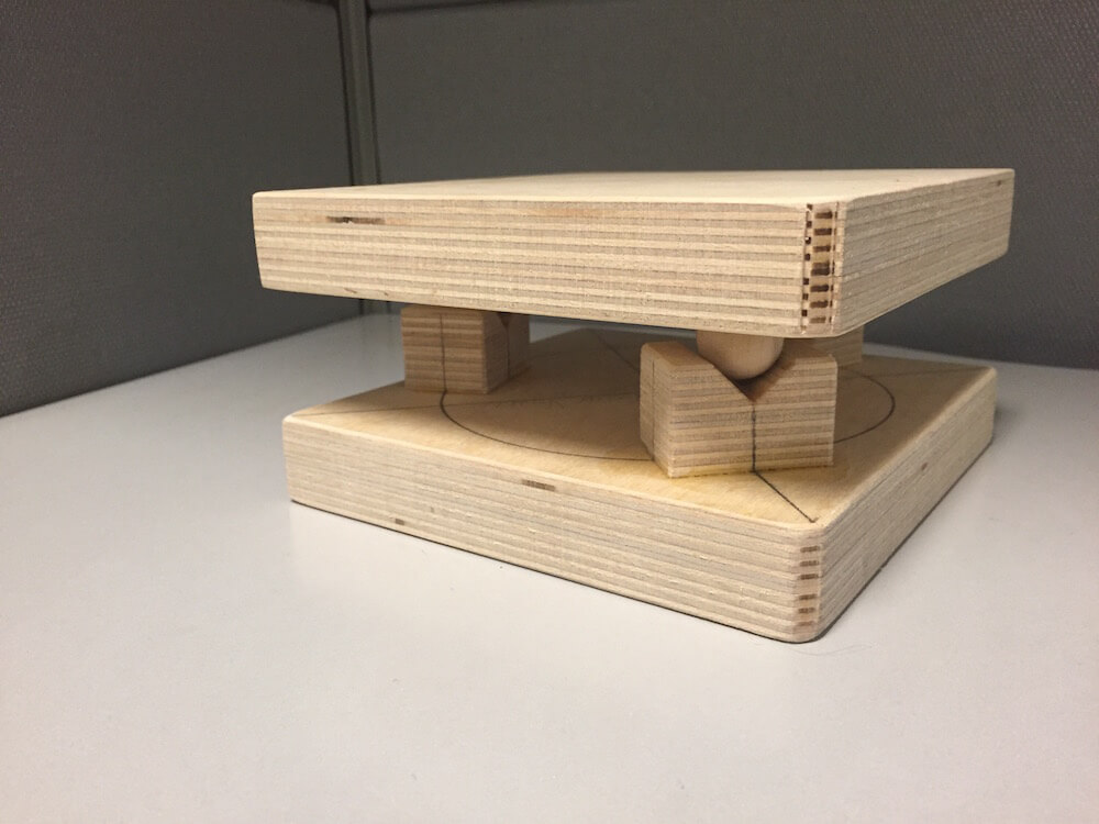
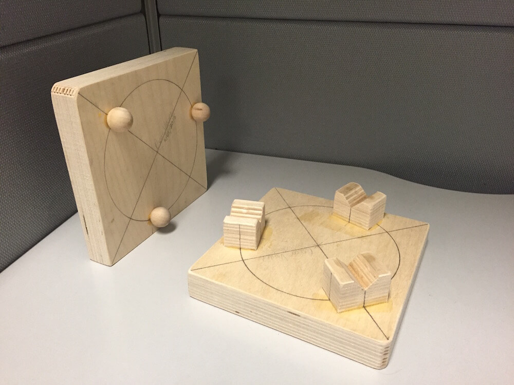
As you can see, the device is built out of plywood, with solid wood balls for the interface. The design is fairly standard, a typical 3-ball-and-groove with 120 degree offset on the grooves. The spheres are 3/4" in diameter, the grooves are cut at 45 degrees, and the coupling diameter is 5". Here's a copy of my original report:
This Kinematic Coupling was built as an educational tool, to experience the benefits and limitations of such constraint systems thru touch. However, applications in precision machines could include the accurate and repeatable placement of tools, stock material, test arrays and any number of other components.
Part 2 - PREP
Team Review and Feedback
As part of my focus for this week was to go deeper into the characterization of my kinematic coupling, I shared my original design report with Aaron and Julian. They offered some excellent insight on possible sources of error and limitations of my original testing which I had not discussed in the report. One such instance was the fixturing of my sensor as part of the metrology setup. Another was my choice to introduce an interface layer between the device and the sensor, as this would introduce compliance and sources of error that should be accounted for and discussed in accordance with the sensitivity of the system and the measurement being made. In other words, adding paper thickness when measuring in inches won't matter much. When measuring in hair's widths? Maybe a little more. They also suggested going into some more detail about the loads applied. I'll try to address them in Part 3.
Another great takeaway from this week's PREP session was our discussion about the assignment's testing requirements. More specifically, while we all had very clear ideas of how to evaluate stiffness and repeatability of the system, I wasn't very clear on how we could approach the assessment of accuracy on its own.
We started with some back-and-forth on how we have considered the measure of accuracy in lecture. My recollection pointed to the variable error along an axis, which you could consider as displacement over the length of travel. However, in a kinematic coupling, the two sides of the device come into place such that there would be no relative motion. So, instead of thinking about accuracy as "staying on target", we should think about the more direct "landing on target". The argument boils down to whether you could build a replacement for one side of the coupling, such that the end result would match the original.
If you were making a tool holder, for example, the tool bit would come to rest at the same location with either the original or replacement set. By the way, it took me a little while to realize this was what Aaron was trying to say, and it was only when we talked about an example (it was about optics and lenses) that it clicked. The catch here is, my original design wasn't trying to line up lasers for an optic system, so what was most important was that I could get consistent results. If I needed "accuracy" then, couldn't I just sand (remember, my KC is made out of plywood!) the replacement down a little bit at a time, until it was a match? Yes, of course! The game has a name, and it's called calibration!
In the end, the discussion came down to our agreement that the device's accuracy would be determined by manufacturing tolerances and calibration. If your application is highly sensitive, such as aligning lasers, you'll have to account for these as part of your design specifications - and your budget!
Part 3 - Rework & Updates to Part 1
An Updated Metrology Setup
Here are some pictures of my original measurement setup:
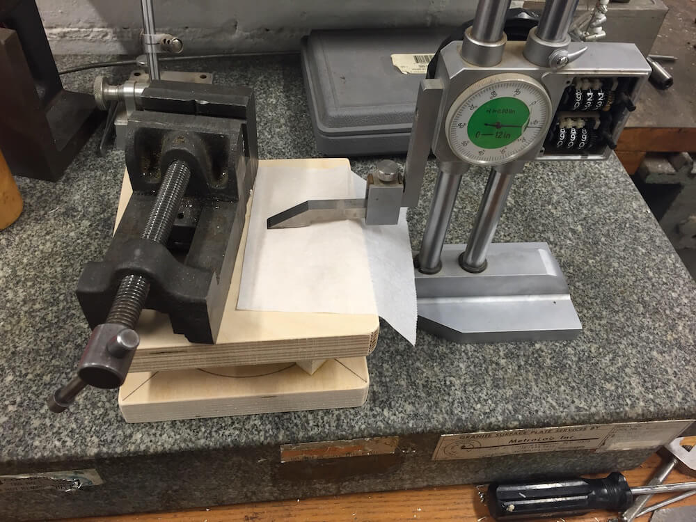
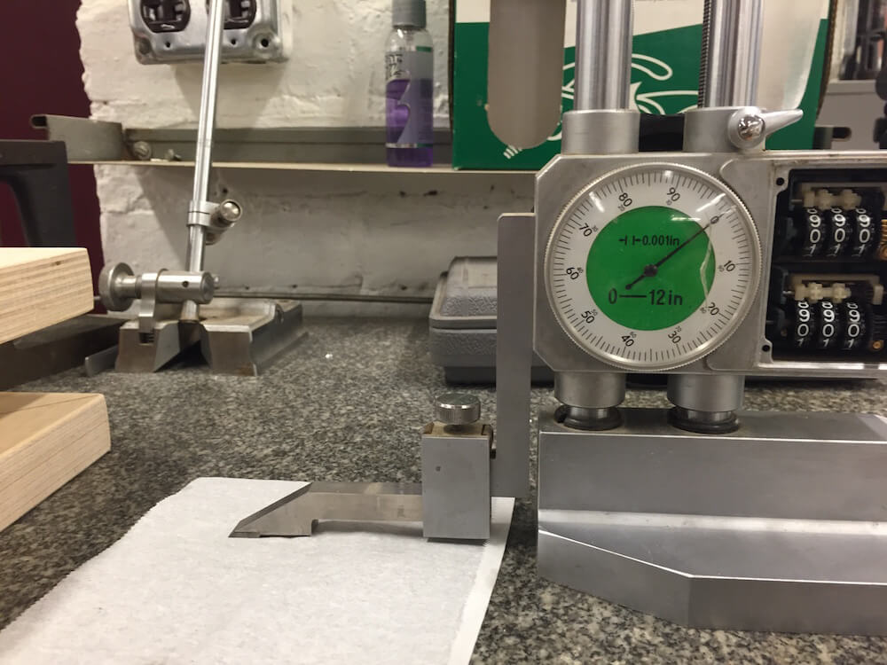
One of the main challenges with this setup, and my reason for introducing an interface layer, was that the height gauge wasn't fixed to the surface. The paper, then, was meant as a telltale for contact in order to avoid lift-off. So, as part of the present revisit to the task, I got my hands on a magnetic base for a dial indicator, and a reliable surface to place it on, such that I could keep the coupling on the granite surface as a reference ground.
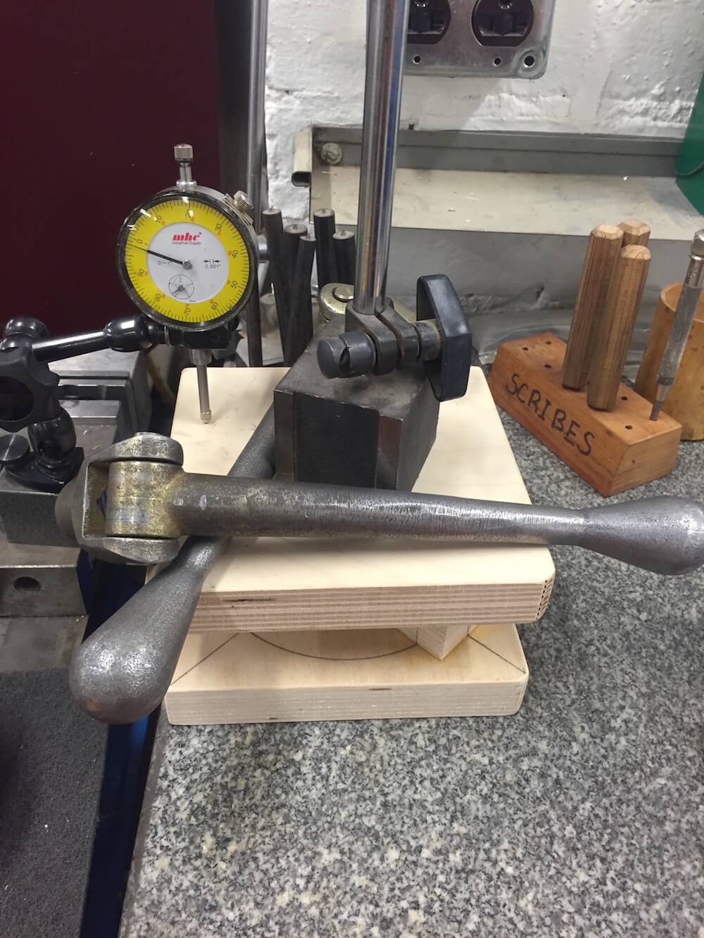
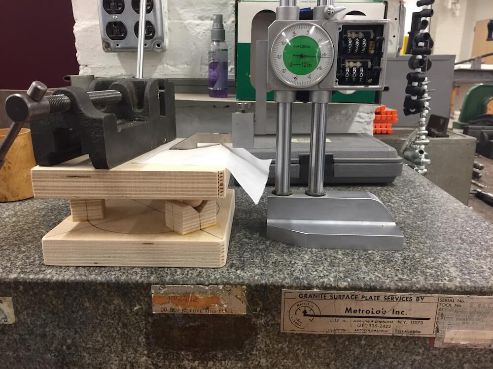
The image above shows the setup with the dial indicator. Another consideration for this round was that I may have not been attentive to where on the top surface I took measurements from the first time around, so I tried to keep the sensor's tip on the same spot of the device for the new set of measurements.
Measurements
I ran a few measurements with different loads on the device, to check its stiffness. As shown in the image above, I used vice handles, mag bases and other parts I found around the shop. After running them thru the scale to know what load I would be applying on the system, I placed them atop the kinematic coupling in its metrology setup, to get the corresponding deflexion.
| Handle 1 | 820g |
| Handle 2 | 880g |
| Mag Base | 1320g |
| Bolts | 450g |
For example, the max load of 34N resulted in a displacement of .00175" - checking the system's stiffness results in 0.79N per micrometer.
Looking at repeatability, the new dataset suggests that the device might be performing better than I had originally measured, giving added significance to the limitations of the earlier values as pointed out by Aaron and Julian. For reference, my original report presented an absolute-value error averaging about 16 microns. However, comparing both old and new datasets, it becomes apparent that the error measured is derived from the final digit of the measurement instruments. As such, a system with a better resolution would be preferred and recommended for the future. Also, a larger number of samples should be collected.
Revisiting the Calculations
I've spent some time working thru the Kinematic Coupling Design spreadsheet, trying to better understand the results from my original measurements and the ratio between testing and design. One of the first things I noticed as I revisited my prior work was that the spreadsheet included an angular shift for the input force that I had not noticed the first time around. There is a load of good information there, after all, and it is definitely easy to get lost in it the first time around!
As I sought to replicate the predictions from my original report, I also realized that while I had made some changes to the input load thru the original design process, the loads weren't quite a match to the testing conditions. It appears I had run my calculations thinking of loads up to 1000N. Modifying the spreadsheet to match the testing conditions results in predictions of about 3micron vertical displacement. Definitely looks like I'll need to take some more measurements to check on this. Maybe I'll get my hands on a laser pointer and use that as an error amplifier. Abbe errors can be helpful, see?
Other Considerations and Resources
This week I had the chance to speak with a good friend and fellow graduate student who had a different spreadsheet - a different tool for the design of Kinematic Couplings. I secured a copy from him and, as I worked my way thru the analysis, made a point of comparing both tables. It's worth noting that one of them excludes displacement due to preload, while the other includes it. Here's what these things look like:
As part of that same conversation, Marcel suggested I take a look at JPE's one-pagers. He pointed out one he had around, that talked about Hertz Contact. I found these to be quite helpful and valuable resources, as they present loads of information and relevant equations in a very clear and concise manner. Here's a link if you want to check it out: