Part 1 - Initial Development
A Little Background
As I began looking for inspiration on what problem I would solve, I took to the time I've spent at the machine shop lately as a reference. In particular, I realized I'd recently spent some time thinking about taking my crafts to the next level. I enjoy woodworking, and my more recent projects would qualify as desk accessories - I started making pens, but have plans for letter openers and other products in this same scale. I have been exploring the potential of creating my own laminates, adding colorful accents and lines to the pieces by using different types of wood. But what if I could engrave a drawing or design of my choosing to the pen? Perhaps I could even consider making parts with embossed designs? Perhaps I could even make a chess set?
There is certainly a beauty to doing all these things by hand, but there is also great potential for greater detail when using a tool specifically designed for this purpose. Even then, the machine could prove helpful in creating a layout, upon which I could then manually burn or carve the features I wanted. I have put some thought into using the laser cutter at the Hobby Shop to try etching a name on the side of one of my pens, tho the round profile and small diameter might present a challenge. Moreover, the user would not be able to reach the full span of the barrel, but would instead be restricted to a narrow band along the axis of the pen.
Surely, there might be tools out there designed for this very purpose, but they are not readily available to me. Now, note that I've considered the potential value of designing a generic multi-axis platform onto which one might add any flavor of actuator (within specifications) to end up with a mill and a 3D printer and a laser cutter, all in one. But, the challenges of such design go well beyond reach for a single-semester design project, for it would require a level of modularity too costly for my current budget.
In very general terms, the goal is to design and build a useful machine by the end of the semester. As such, the desire for a more specialized tool paired with the project requirements render this the perfect opportunity to build a machine that meets my own choice of functional requirements. So, let's begin!
The Problem Statement
I want a machine that will allow me to bring new detail to the pens I make. At the very least, the machine should allow me to mark up a design onto the piece for posterior carving or burning. If possible, it may even be worth enabling the machine to do the carving or etching itself.
Currently, there are accessories that may be added onto full-scale lathes for indexing. 5-axis mills are also perfectly capable of completing this task - for a high price!
Plus, I would like to build a useful tool out of the scrap material I can find at the shop, to breathe new life into all those leftovers. Oh, and because building things is fun!
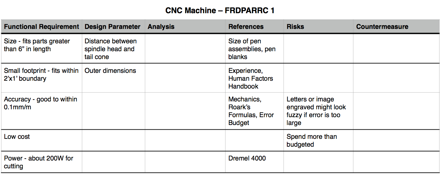
Functional Requirements
Here's my initial list of functional requirements:
- Fits pens and parts longer than 6"
- Has a small footprint (let's say max 2'x1')
- Is accurate to within 0.1mm per meter
- Low cost
- Power?
Under the assumption I do end up deciding I want my machine to include a cutting element , I have looked at Dremel tools for reference on how much power it would take. Considering the type of carving one might achieve with these handheld rotary tools, I think they are in the right range for my application. The Dremel 4000 has a 175W motor, and variable speed from 5,000 to 35,000 rpm.
FRDPARRC
Forces
To get the forces, I'm assuming I'll be using a Dremel 4000 or something very similar to it. For the sake of a first order calculation, I am thus assuming I might use 200W motor with a 9mm tool bit at about 10,000 rpm.
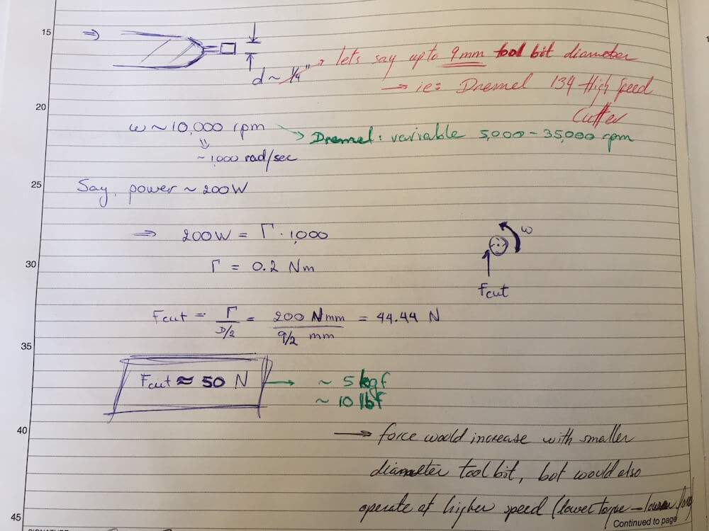
The resultant cutting force is approximately 50N.
Machine Stiffness
To get the machine's required stiffness, think about it as a spring! If your machine is an ideal linear spring, and you know the forces the machine will experience, plus the maximum allowable displacement (which you get from your accuracy), then you can solve for the stiffness. Remember Hooke's Law? Well, my force is 50N (from above), and my allowable displacement is given below according to the desired accuracy for a member of length 12" - which is the maximum length I expect to have between the spindle head and the tail cone holding the pen. Note that I refer to these parts as they would fit in a lathe, for visual effect (the pens are, after all, turned on a wood lathe!). However, the cutting tool for this machine would actually have a spindle of its own; the machine's rotary axis would operate as a position-controlled element Think of it, if you will, as a cylindrical-coordinate mill. I've considered two accuracy scenarios here:
| Accuracy | Displacement | Stiffness |
| 0.005in/ft or ~0.4mm/m | 0.13mm | 390 N/mm |
| 0.1mm/m | 0.04mm | 1250 N/mm |
Structural Loop Analysis
In the previous section, I mentioned that I am expecting to build a machine with a 12" span for the cylindrical parts. That is double the range listed in the FRDPARRC table, in order to accommodate any supplementary accessories I might need, such as a mandrel or bushings to keep the pen in place. The extension would also allow me to work on slightly longer parts in the future. That would be about 300mm. Between the range of motion of the parallel-axis carriage, the cutting tool depth slider and any minor adjustments I might add, let's say the sum of the axis travels is about 400mm.
We can then assume that the structural loop will be roughly about 3 times this sum of travel ranges, so 1200mm. If we further consider a cylindrical beam of diameter L/5 = 240mm and wall thickness OD/20 = 4mm, we can compare the expected stiffness to the required stiffness. Modeling the machine as a cantilevered beam, we can extract the equivalent stiffness in terms of the modulus of elasticity, beam length and area moment of inertia. The equation then gives an expected stiffness of about 6700 N/mm when using aluminum for the frame. This is well below the required stiffness, even for the better accuracy scenario listed earlier!
If we modeled the structure as a c-shaped beam, then we could extract the effective stiffness from the deflection equation for curved beam bending, as a function of the beam's radius instead of the length as in the typical cantilevered beam. The equation may be found in Roark's Formulas for Stress and Strain, and is derived from Castigliano's 2nd theorem (energy method). The resulting stiffness is 38400 N/mm, much higher than that of the straight cantilevered beam.

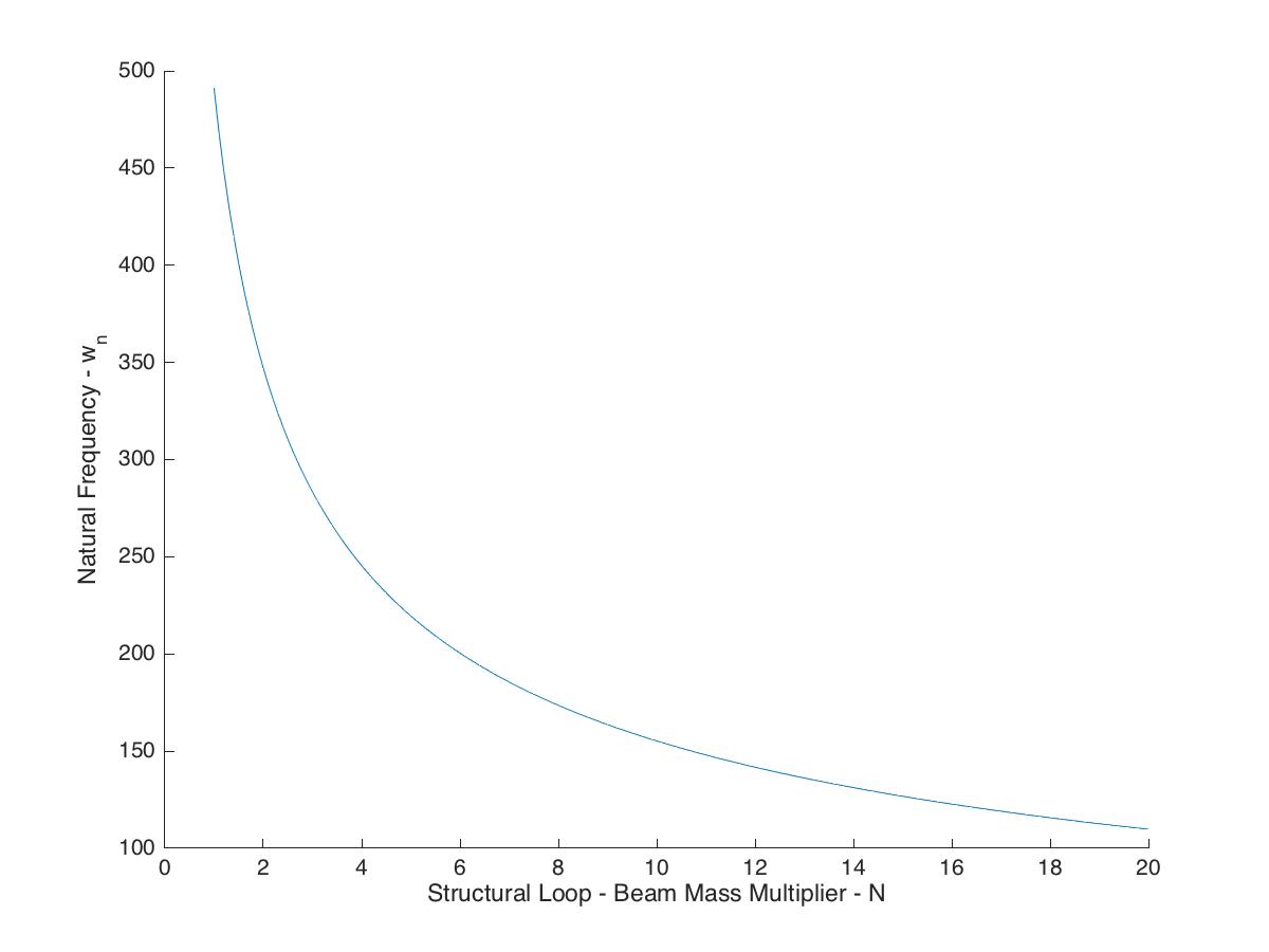
Natural Frequency
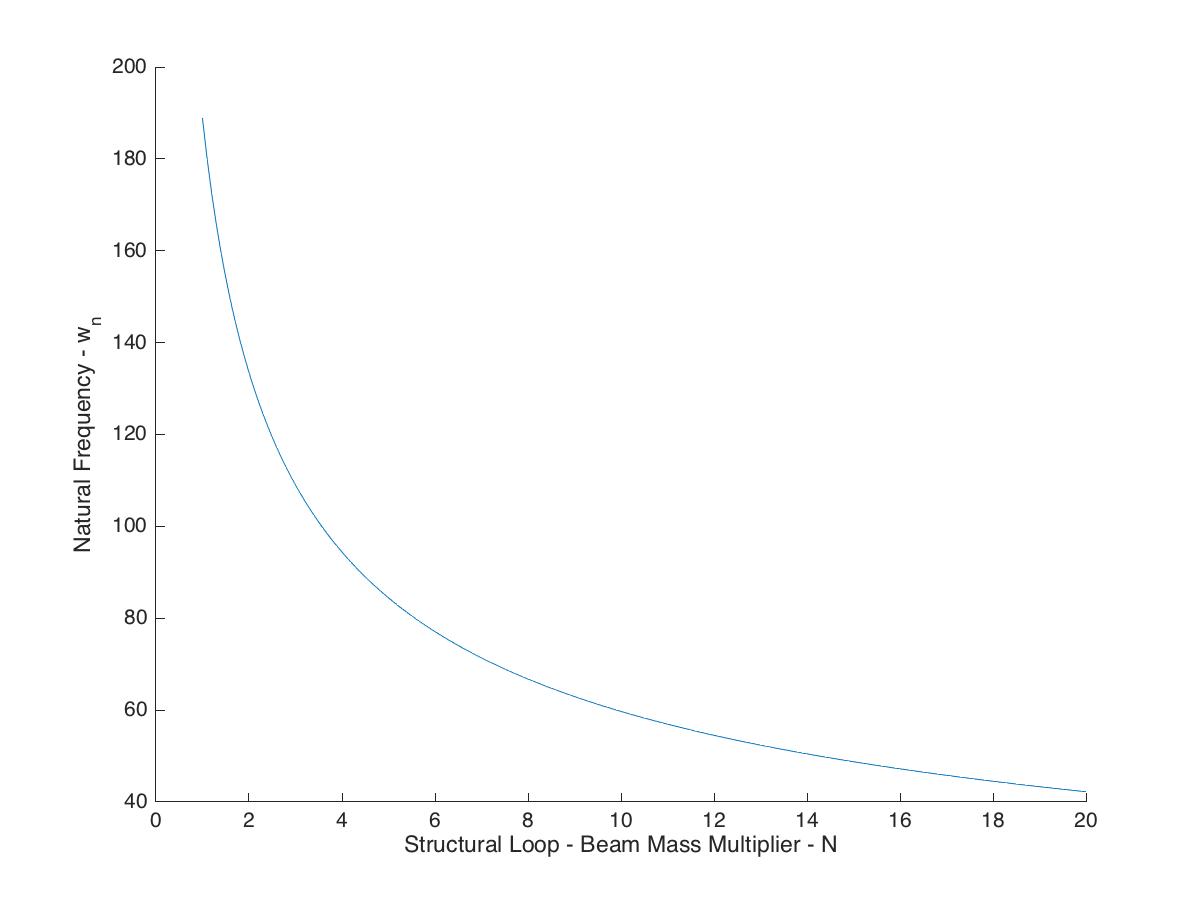
We can estimate the natural frequency of the machine from the structural loop, taking into consideration its mass and stiffness. For a first estimate of the mass, let's consider the beam detailed above, with length 1200mm, OD 240mm and wall thickness 4mm. If the member is made of aluminum, then we can solve for a mass of about 28kg. Let's say the total mass of the machine is some multiple of this value from the structural loop estimation. The following plot shows the natural frequency as a function of this multiplication factor N.
Part 2 - PREP
Team Review and Feedback
This time around, my peers provided some incredibly helpful insight and references to the challenges and benefits of my various ideas. Since my original plan involved a modular (sort of all-in-one) platform, I had made a few notes about what sorts of features I would add on. To my comment on polishing wheels, Aaron immediately thought of flattening plates and mentioned Blanchard grinders - to which Julian remarked on both the awesomeness of the concept and the challenge of proper dust collection. I think I'll make my machine a bit more specialized for the late-stage woodcraft detailing applications for now.
As one of my ideas involves using a wood-burning set as the end effector, I made a few notes wondering how best to compare these forces with cutting. Aaron had some excellent feedback on this matter, commenting on the specific cutting energy of metals.
Also along the lines of the wood-burning tool, I'd made a list of approaches I might consider in lieu of a position-control system for the tooltip. One of my ideas involves some sort of force-control loop to keep the tip in contact with the part, without damaging either. Think about how you hold a pencil against the paper. By the way, this might be another form of tooltip for my machine, if I end up just doing tracing. In any case, my peers added a few more types of actuators I could use to this list.
Julian had a few more comments on the controls side. Since I might be dealing with variable diameter profiles (which I would like to preserve), I should look into point mapping and design wrapping onto a surface. He also shared some contact information for an instructor of his who has some experience on this area. Great!
While not strictly part of the peer review in the traditional sense, we had the opportunity to brush up on some aspects of the analysis required for this assignment and revisit our work as we saw fit. I have taken the opportunity to rework a few aspects of my design and to draw a few more rather valuable conclusions from the updated analysis. These additions to Part 3 will begin with the review of machine stiffness and expand from there.
Part 3 - Rework & Updates to Part 1
Strategies and Error Apportionment
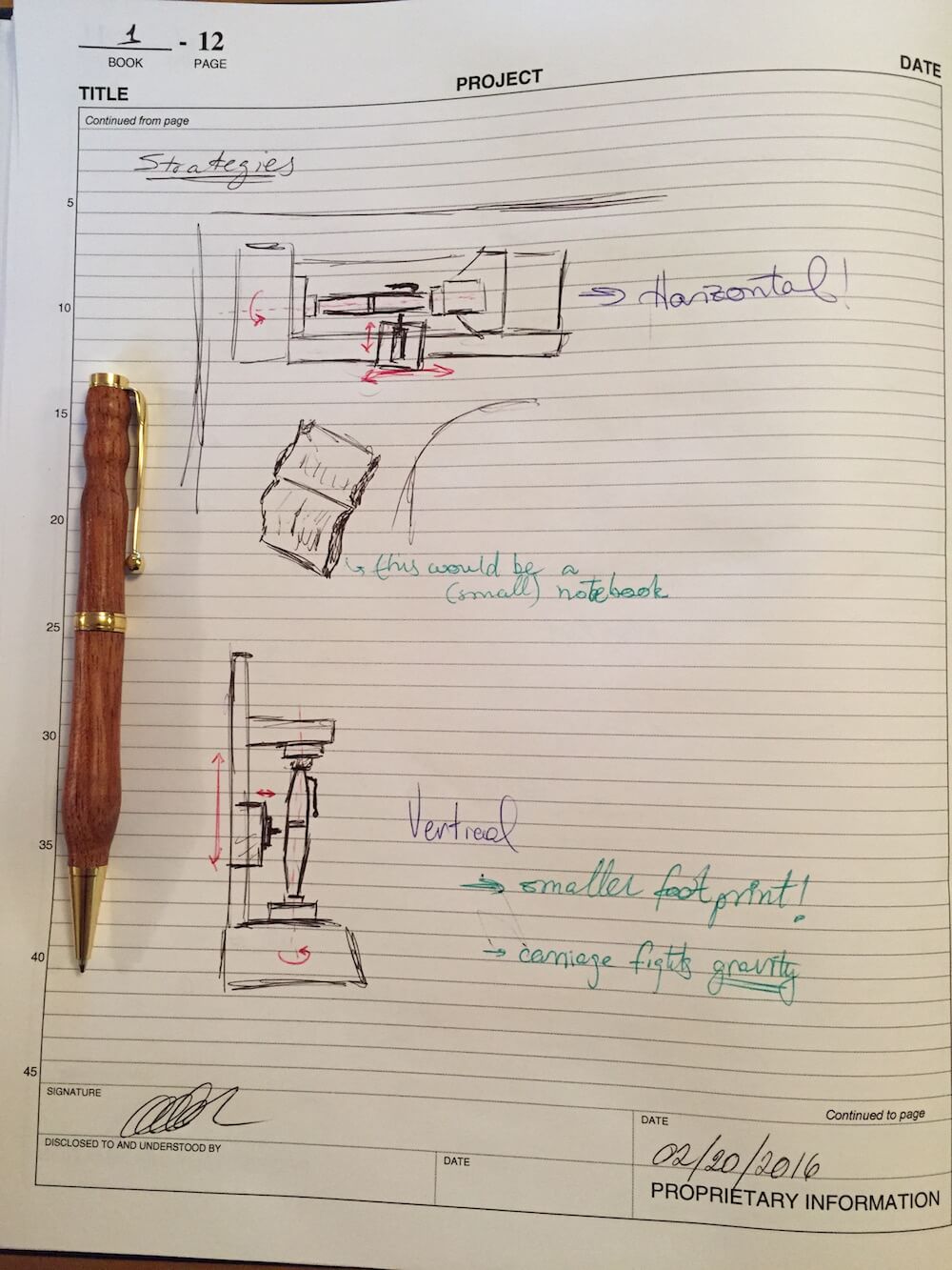
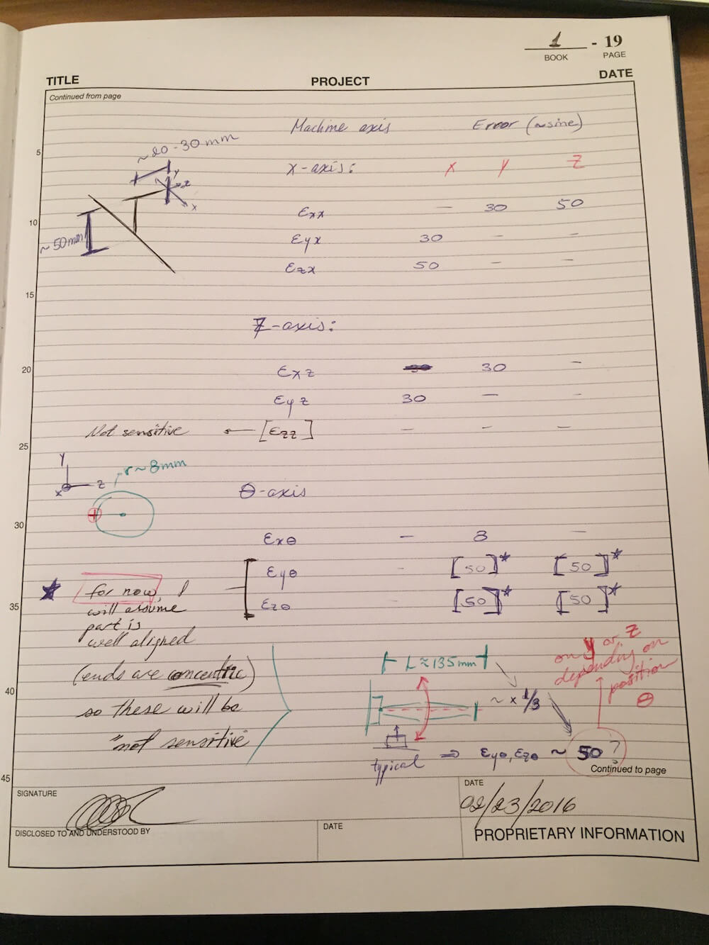
Here are some very high-level sketches of strategies I am considering:
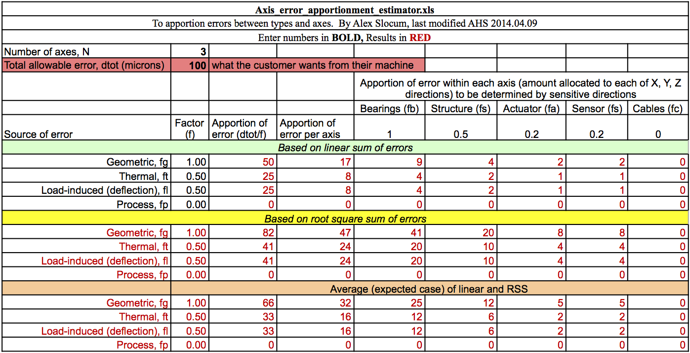
Using Prof. Slocum's error apportionment spreadsheet and an estimated allowable total error of 0.1mm:
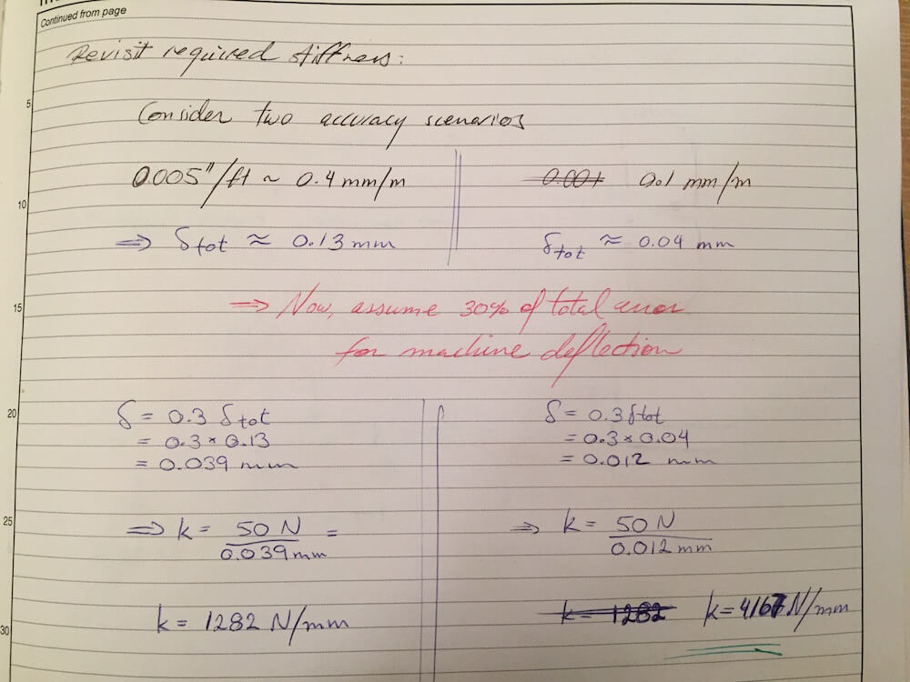
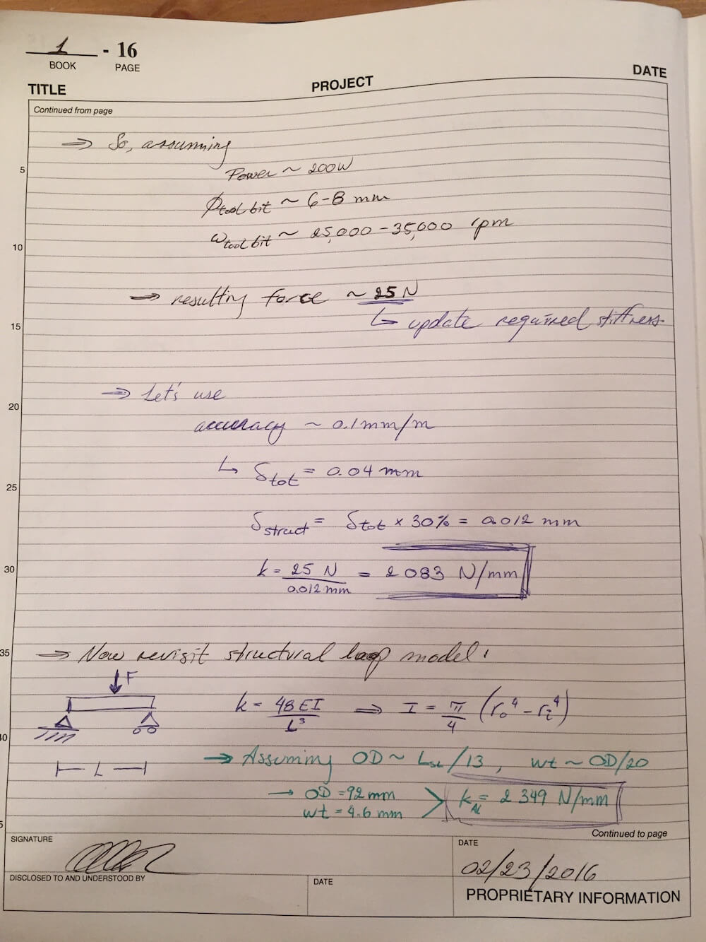
Revisiting the Machine Stiffness Requirement
After reviewing a design example, it came to my attention that I had not scaled the allowable error before evaluating the required machine stiffness. For this purpose, I will start by using an estimated 30% of total error as the portion allocated to machine deflection. This should be roughly on par with the error allocated to structural components on the error apportionment table above.
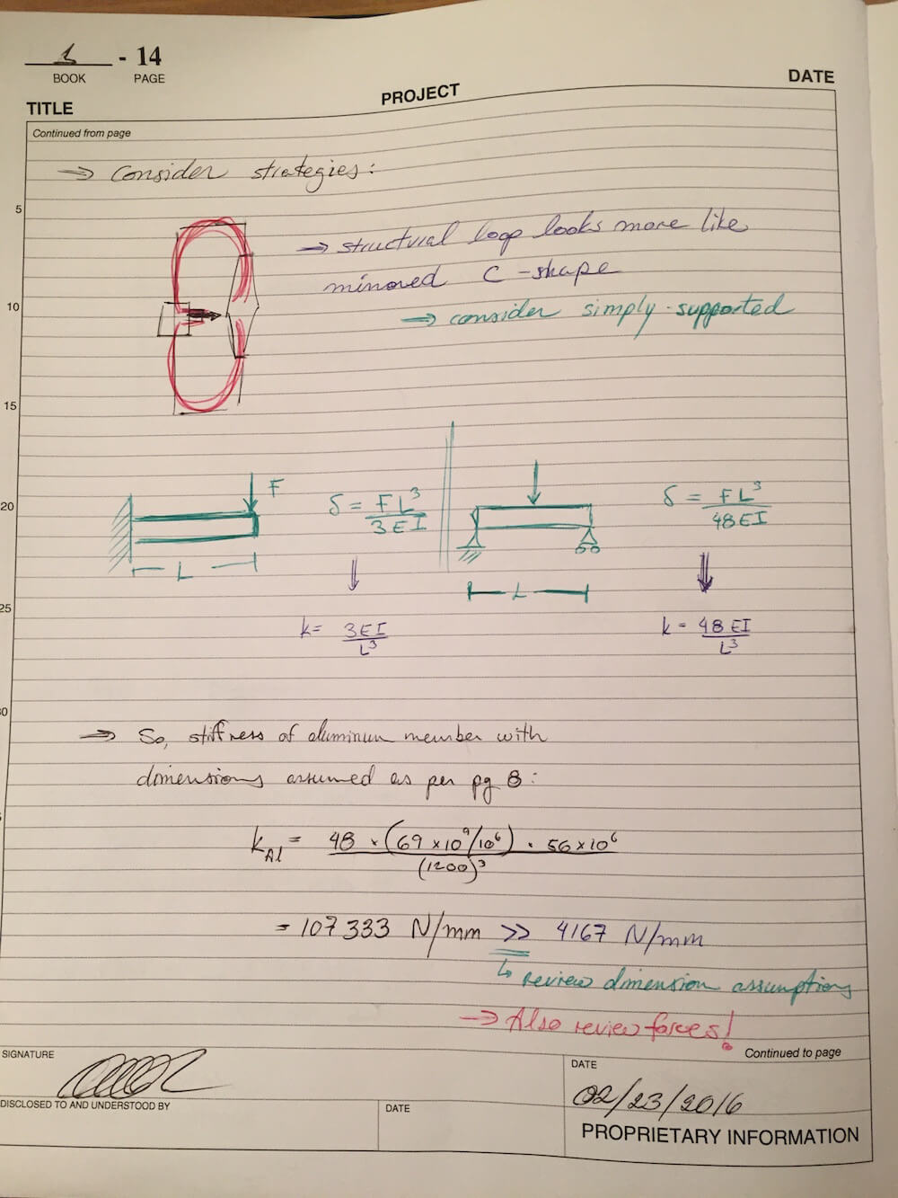
Revisiting the Structural Loop
For the structural loop, it seems reasonable (per the sketches I made for the strategies) to consider a simply supported beam instead of the cantilevered beam discussed earlier. This would change the effective stiffness of the structure.
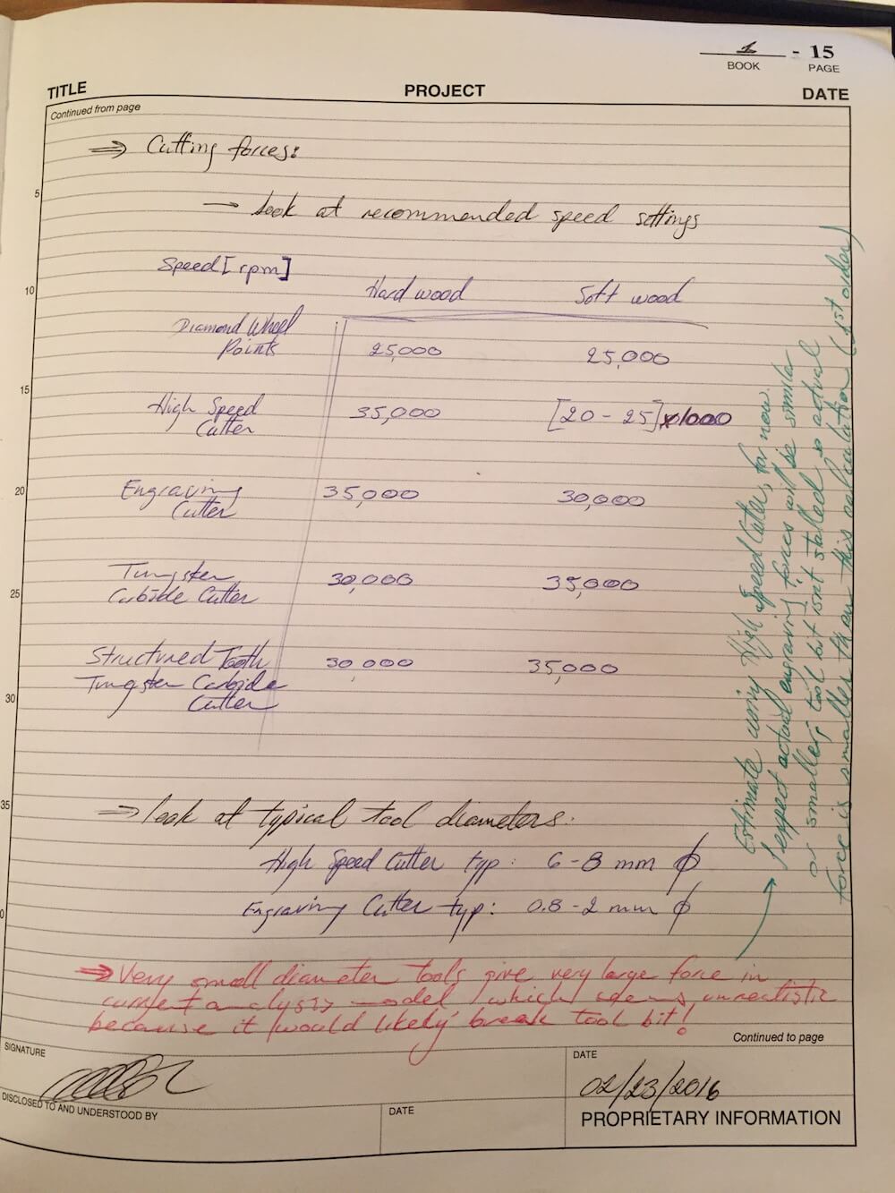
Revisiting the Cutting Force
I've also taken another look at cutting forces. While the particular loads associated with engraving will require some further research, I've put together some reference material based on the tools and speeds I expect to use. In particular, the typical diameter and recommended speed settings for the cutting bits I would expect to use are 6-8mm and 25,000-35,000rpm respectively. For a 200W motor, this results in a typical cutting force of about 25N. I have updated my spreadsheets for the structural loop accordingly. I have also modified the assumptions about the size of the tube used for the structural loop to more closely match the required machine stiffness, and have reviewed the natural frequency plot.
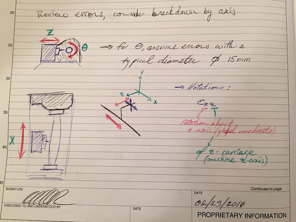
Revisiting the Errors
Going a little deeper into the error apportionment, looks like the next step is to figure out how to distribute the error budget across the different axes of motion.
Other Considerations
Given the application for which my machine is intended, I have also taken a first look at the effect of the cutting force as applied on the pen itself. For this first calculation, I have started ignoring the pen barrels themselves and applying the cutting force on a 7mm steel mandrel that supports the pen sections. Assuming the length of the mandrel is about 135mm - a good approximation to the length of a typical pen - and modeling the mandrel as a simply supported beam, I find a deflection of about 0.05mm, greater than my desired total error.
While this is only a first look at the system and does ignore some of the complexities of its geometry, it suggests that I should proceed carefully and perhaps consider at least one of the following:
- Revising my desired accuracy and allowable error
- Providing support for the pen structure to reduce the unbraced length
- Revisiting my cutting force predictions
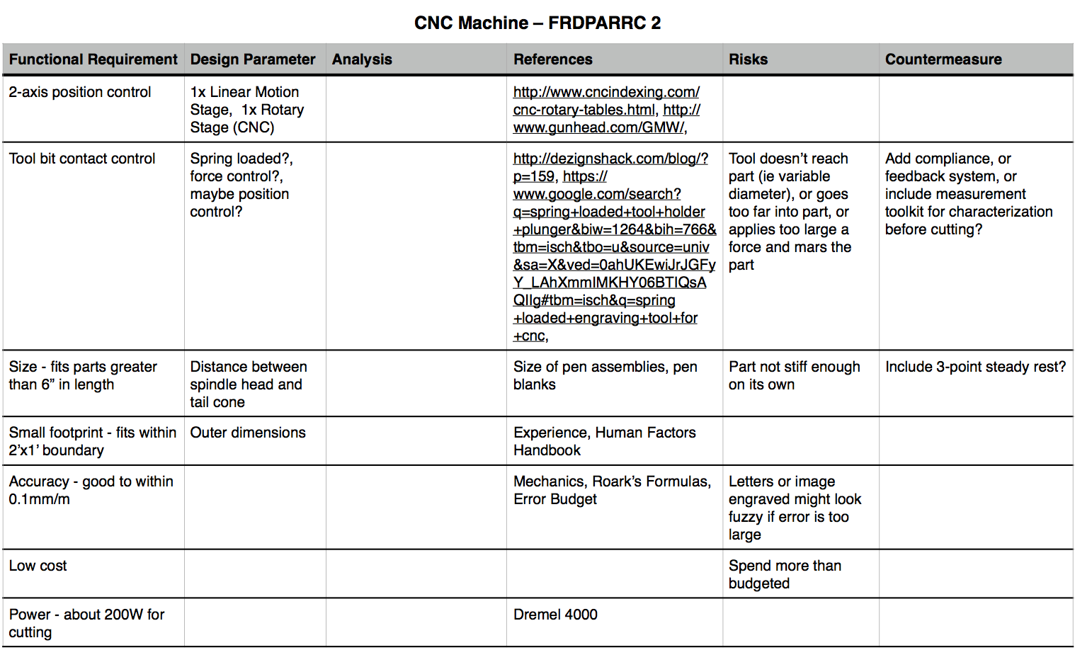
Updated FRDPARRC
Here's an update to my FRDPARRC table: