Part 1 - Design Report
Motivation
Mechanical systems can become very complex in certain industries and applications. The performance and reliability of the system will depend on the numerous details coming together, and having a solid foundation of design fundamentals can prove critical to the success of the product.
As part of the 2.77 experience, we (the students) have been challenged to make use of these very fundamentals and a deterministic design philosophy to achieve a rather ambitious goal: in a single semester, each one of us was to build a functional machine based on the design requirements we deemed appropriate for our application at the beginning of the semester.
Problem Statement, Strategy and Concept Development
I believe hobbies are a valuable aspect of life, and count woodworking among my choices of spare time activities. Drawing inspiration from this craft, I decided to build a machine that would enable me to bring a new level of detail to my work. An engraver, with which I could add various designs to my parts, or even carve features for inlays.
The problem I intended to address with my machine was that, while I have easy access to lathes and mills on campus, these machines would not grant me full control over a cylindrical surface, such as that of handmade pens. The mills would limit me to work on a small section of the piece while held on the vise, and the lathes would mostly restrict me to axisymmetric features in their standard setup.
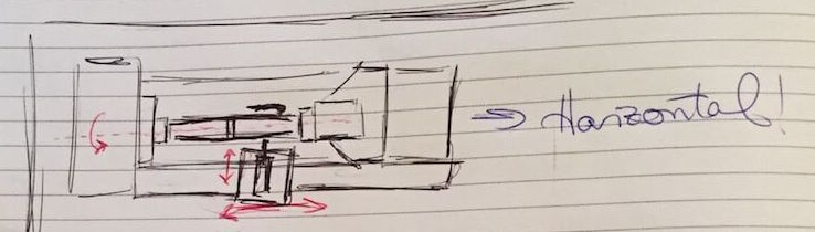
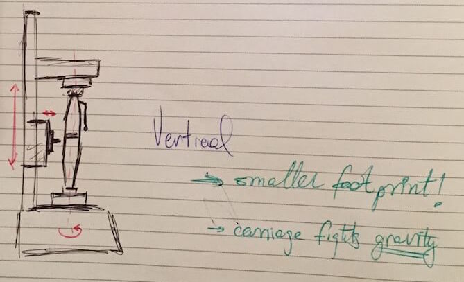
With a clear problem in mind, the next step was to develop strategies to address the stated need. Starting from a top-down perspective, these represented paths for further exploration and detailing. At the earliest stages, design strategies conveyed a general layout and form-factor for the machine:
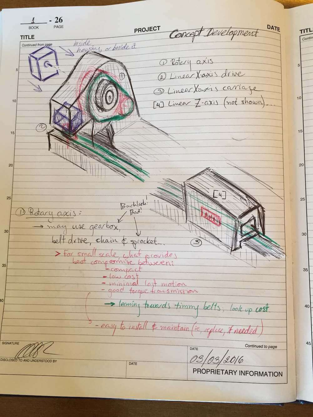
While the strategies give a frame to build upon, the concept development stages start to fill in the gaps, adding detail in gradual steps. For a given motion in a strategy sketch, the concepts would represent ways of achieving it - if you need linear motion, for example, you could add some wheels to the part and make it move like a cart. If that approach doesn't provide enough constraint, perhaps sliding on rails would be better. Here's a sketch of one of my early concepts for the engraving machine:
Another important part of this early stage in the design process was to determine the baseline functional requirements for the product. These would in time become the metric by which the design would be tested and deemed either successful, or...
These requirements included a value for desired accuracy, from which an error budget could be derived for the detailed design and component selection process later on. Here's what such an error apportionment looked like for my machine:
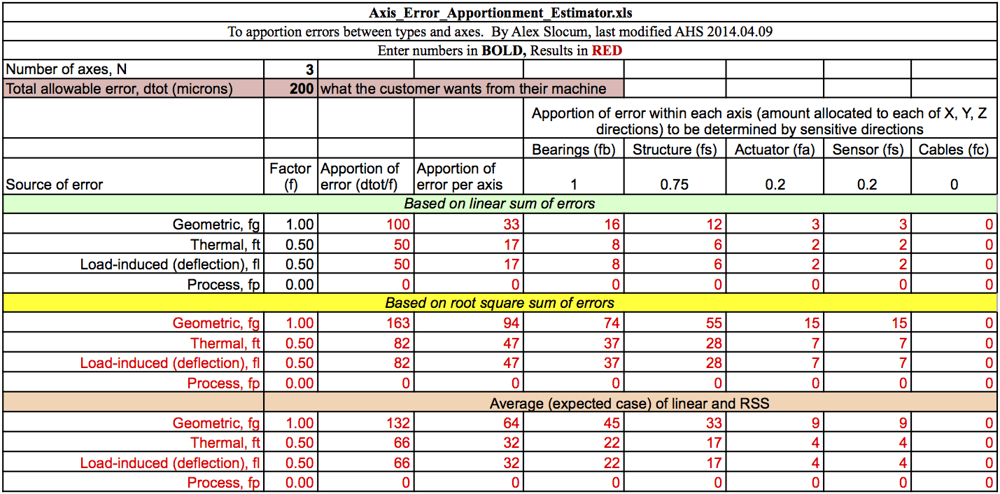
Much like a financial budget, these numbers helped inform design decisions throughout the process. They served as a baseline to determine the suitability of strategies, concepts and components, offering a new light to the added value of that really nice linear guide. Surely it's better, but is it "better enough" to justify the cost? And those bearings, they are cheap, but will they make everything rattly and whacky? How about mounting the rails another half-inch further apart? By comparing the results from even first-hand calculations and geometric error gains, the design process kept moving forward with confidence that the resulting machine would be capable of the desired performance.
Detailed Engineering & Development
First-hand calculations are quite valuable, and certainly help keep things moving forward. Nonetheless, taking a closer look and running more detailed models is also important to ensure that all requirements will be met in the end. Making sure the motors are strong enough, that the power supply can provide enough juice to the machine and that your tool won't break in the process is not something you want to wave off.
A major part of detailed engineering for my machine involved reviewing cutting processes and forces, checking friction loads and reviewing capstan tension capacities. In addition to these computations, I also took a closer look at the structural layout and bearing arrangements, assessing their effective performance against the error allocation from the early design stage. This last part was achieved by using the error budget spreadsheet, which looks at the series of members connecting the tool tip to the workpiece and estimates how these will diverge due to loads and random error in the system.
For cutting processes, for example, I used the following diagram and equations to identify the forces on the system. I then compared the results with my earlier estimates, which were based on spindle motor power alone.
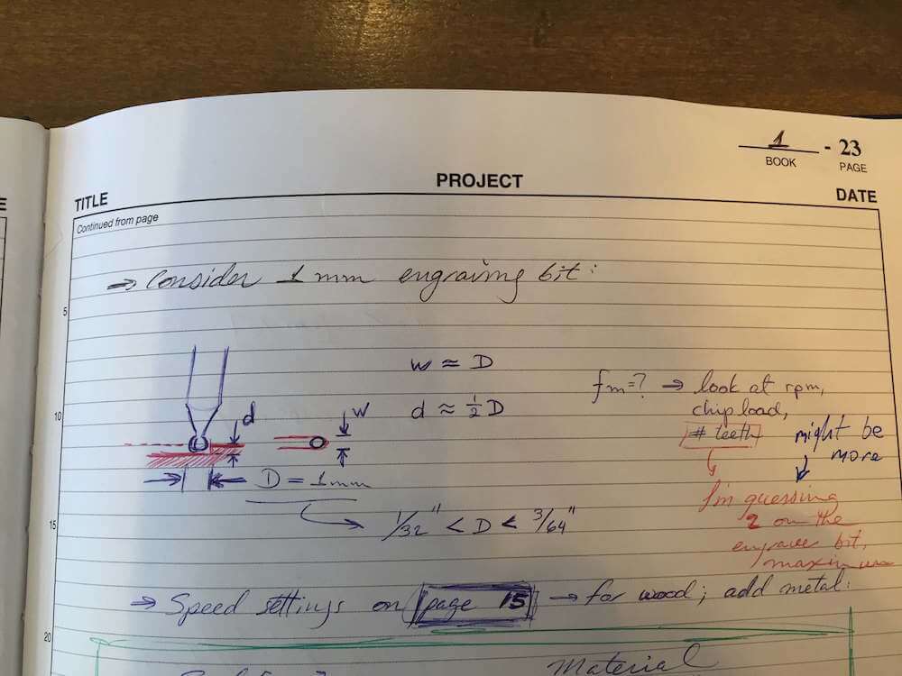 $$P_c = K_p Q$$
$$Q = \frac{f_m w d}{60,000}$$
$$P_c = K_p Q$$
$$Q = \frac{f_m w d}{60,000}$$
Here, \(P_c\) is the cutting power, \(K_p\) is the power constant and \(Q\) is the material removal rate. In turn, the material removal rate for milling processes is calculated from the feed rate \(f_m\), depth of cut \(d\) and width of cut \(w\).
I determined my most critical module was the X-axis drive system, which I had originally designed as a belt-drive. When I took a closer look at belt stretch compared to my error budget, however, it started looking like the odds that I would meet my requirements were about to slim down unless I reevaluated my approach. As such, I opted for a capstan drive system instead. While the belt and cable I compared had similar elastic properties on a sigle segment, I could run multiple loops of steel wire rope more easily, and thus share the load between various segments to reduce the overall stretch on the X-axis actuator-constrained degree of freedom. With that done, I still had to check that I could steer clear of slipping on the capstan.
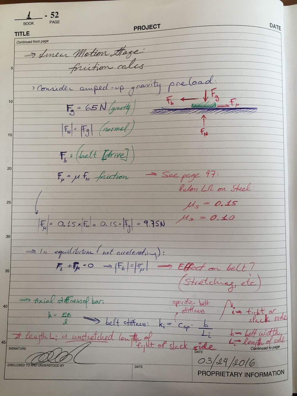
$$T_{load} = T_{hold} * e^{\mu \theta}$$The review of friction loads drew from estimated component weights to draw a reference normal force. Here's an excerpt from my design notebook:
As for the error budget used to determine the effect of machine geometry, here are the results:
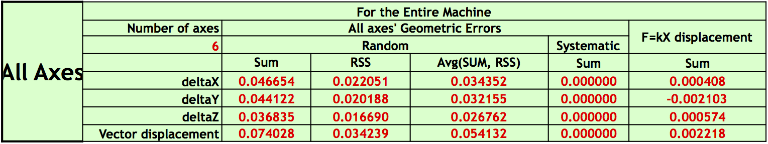
Using the forces expected on the system, and accounting for a factor of safety, I determined that the baseline NEMA-17 stepper motors might not be strong enough to handle the full range of load scenarios. Taking a look at the error budget calculations, I reviewed my sources of error. Since it seemed I was well within the original allowance, I took a look at adding a gearbox and determined that the extra backlash was sufficiently small and thus acceptable in return for the extra torque.
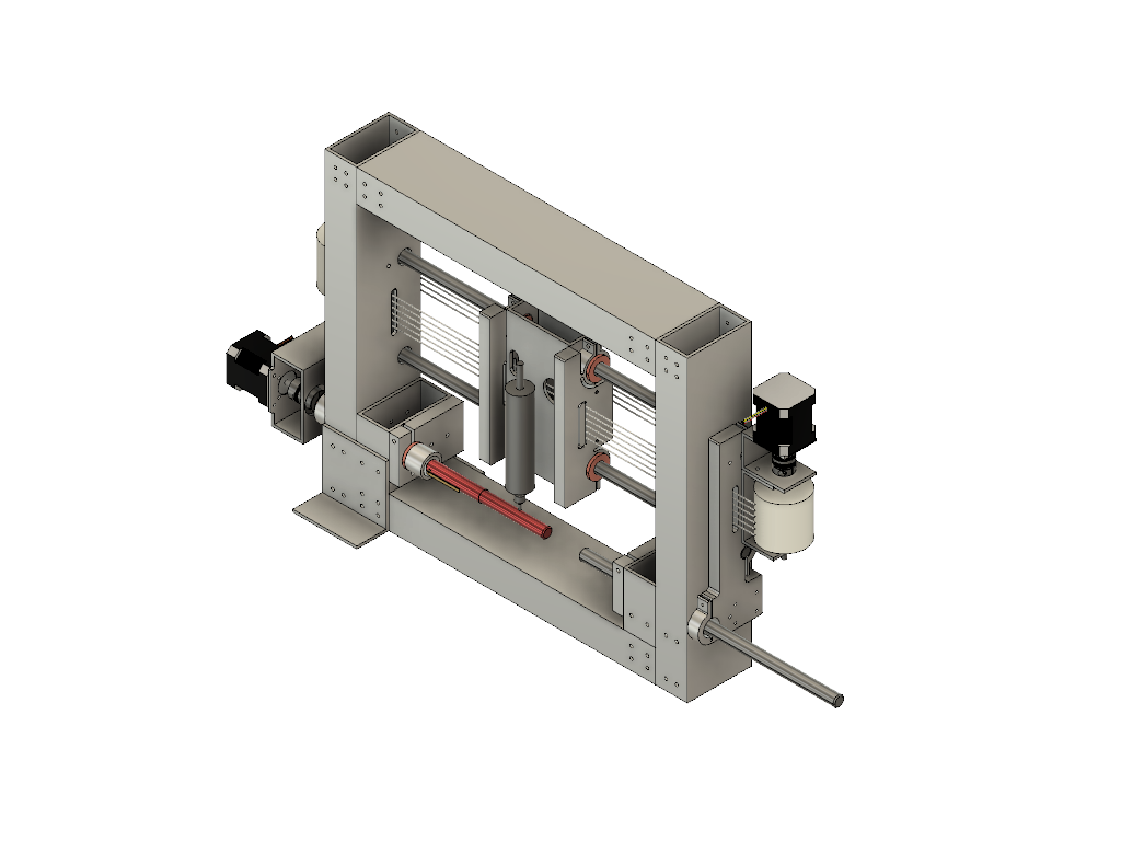
Drawing from these calculations and the error budget, I went on to build a first CAD model of the machine.
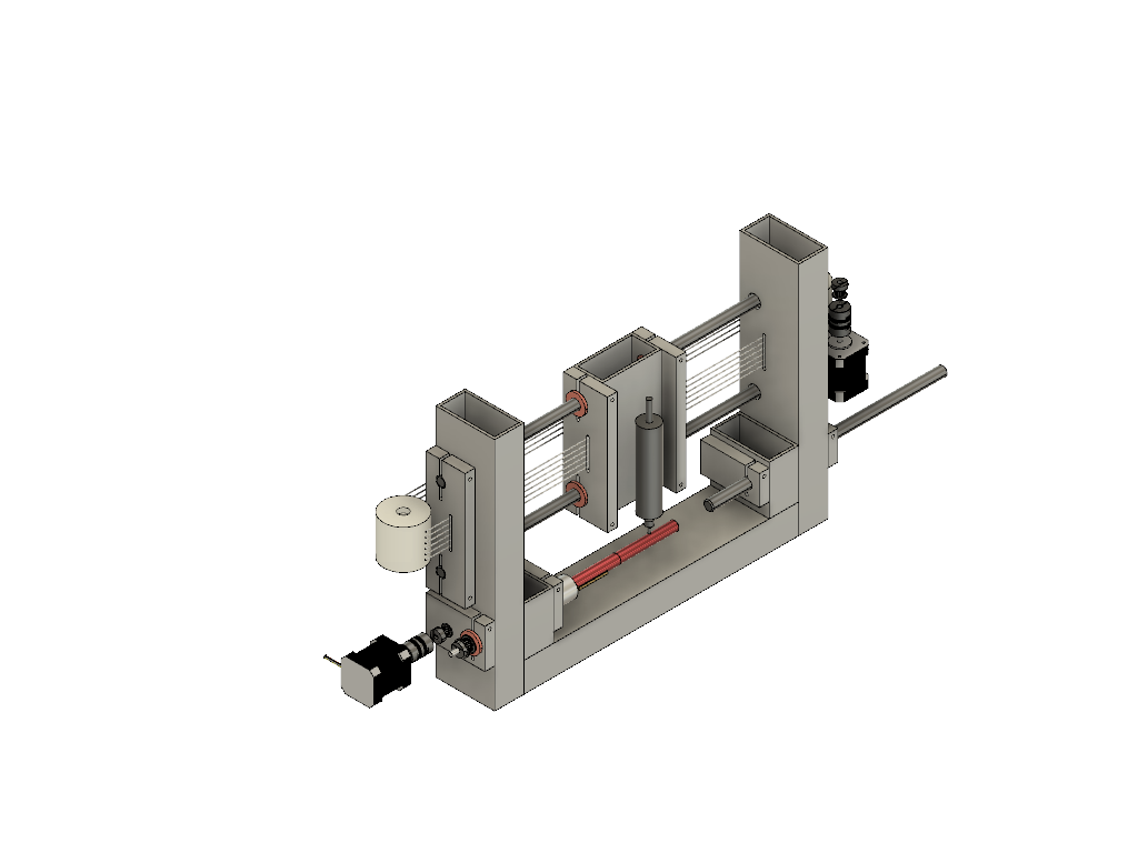
After adding motor and pulley mounts, bracing and tube joints, the model looked like this:
Integration and Testing
Having performed the calculations for the capstan drive, I ran a series of bench-level experiments on the behavior and functionality of the design. One of the concerns raised during peer reviews had been the effect of rope crawl on the capstan during operation. While I had oversized my pulleys with this in mind, it was worth making sure that the long-term effect wouldn't jeopardize the machine. In particular, I mean that the lines would be pulled back into a reference level by the rope clamping system I had added on the carriage. The tests seemed to suggest the design logic was sound, and thus it was time to start building!
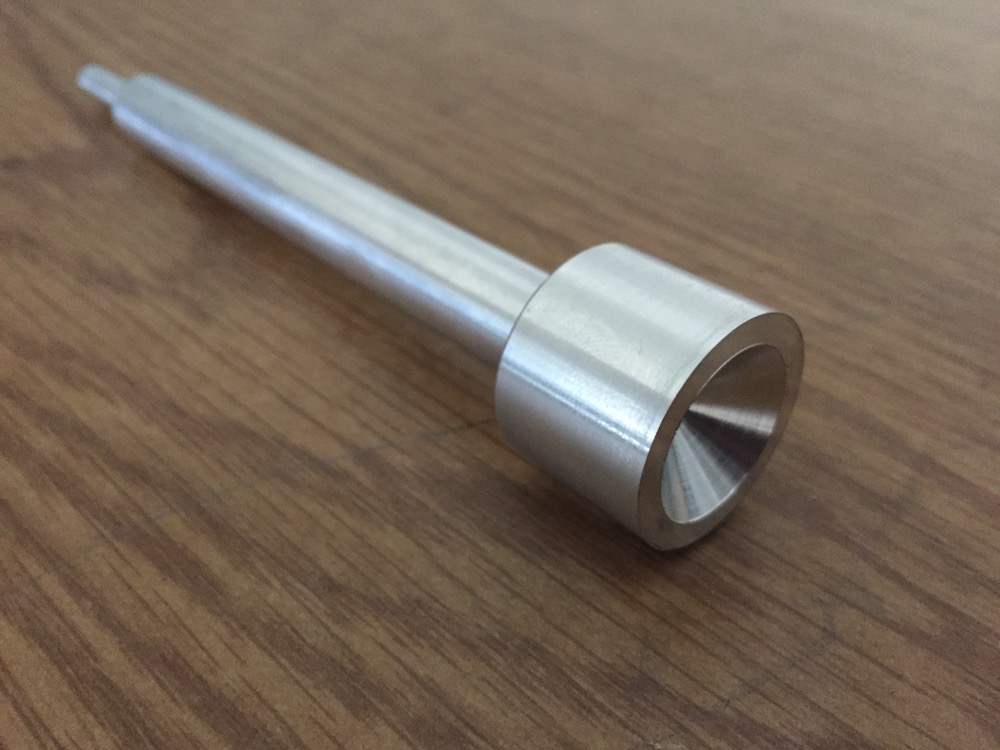
Due to machine availability, one of the first parts completed for my machine was actually the Y-axis shaft:
From there on, parts started coming together. Given that the majority of my more complex parts make up the frame that holds the shafts for the X-axis in place, a good deal of time went into manufacturing, before the machine could be put together.
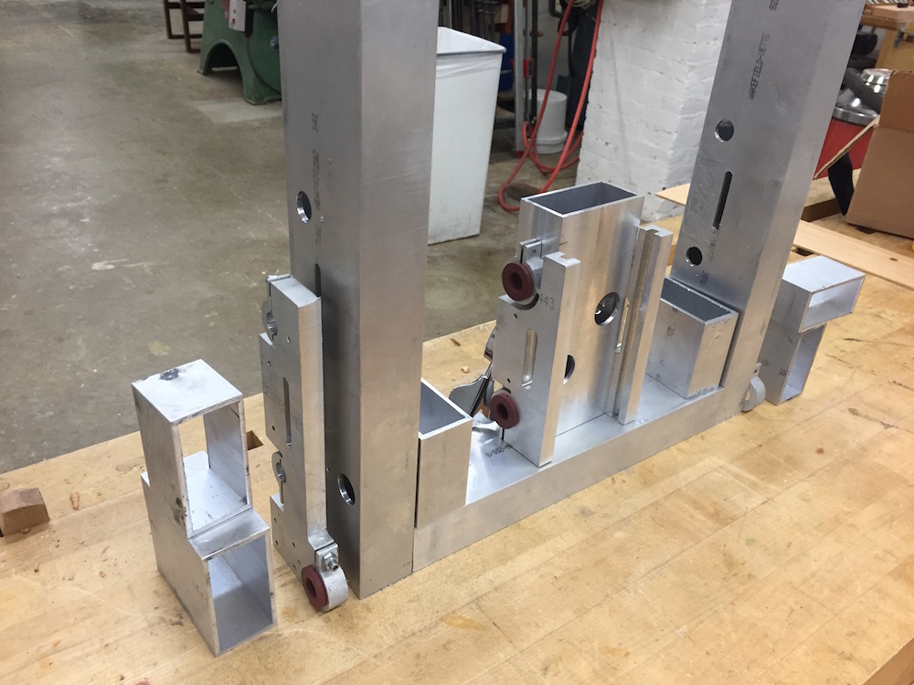
Even after I got the parts ready for assembly and started putting things together, I realized only a little too late that I'd mounted my carriage backwards!
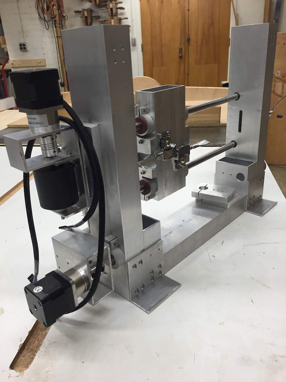
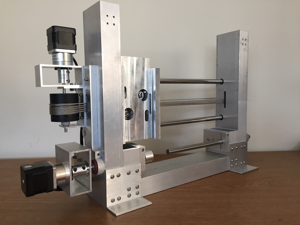
I realized during the first assembly attempt that when I replaced some pins with bolt connections, I should have added more access ports to reach the fasteners during assembly and tuning. Given that I had to reverse the carriage, I used that as my opportunity to add the necessary features on the carriage body. After some last-minute machining, and another take at assembly, here's the machine in its current state:
The first time I connected the motors, I was rather disheartened to see that the X-axis drive started skipping. However, one of the reasons why I had added the access ports to the carriage before putting it back together the right way was that I might be able to tune the system. My design calls for surface replication during the final assembly, where a thin film of adhesive is used to correct minor flaws between mating surfaces. With that in mind, I proceeded to adjust one of the bolts holding the side plates and body of the X-carriage together. Doing so reversed the misalignment between the sliding bearings and released the carriage to the motor. However, the carriage would only travel in the mid-span of the rails. I then turned to the riser plates, which I had not yet trained into position with the drive system. By releasing the bolts for a moment so the rails would settle, then locking them back in place, I was able to further reduce the carriage binding. After some more laps and additional tuning, both on the carriage plates and the riser plates, I managed to clear the entire span of the X-axis with smooth motion.
The machine currently exhibits 2 of the 3 axes desired for full CNC functionality, including the most-critical-module as the X-axis drive system. Having built and tested the foundation of my design, I will continue to develop this system by adding the Z-axis over the next few months.
And as a closing note for the integration and testing section, a must for a machine of this kind: video!
Here's the machine, moving X and Y:
Machine Expo Slides
Here are my slides for the Machine Expo:
Lessons learned and other thoughts
While I am quite pleased with the results to this point, I am aware that there is still some work ahead before I can start engraving. As I keep that in mind, I realize my design is less modular than I would have hoped - a result of walking into the design process with a fixed idea about what materials I believed I could find in the shops and random scrap piles. While I did so hoping to save some money on the project, it certainly proved costly in terms of extra machining and assembly time. Even with the materials I managed to secure, I realize I might have been able to make the design more modular if I had taken just a moment longer to consider other possible configurations. Working on a tight schedule can at times seem too pressing to invest time on a particular point, but it would indeed be an investment worthy of consideration.
Having spent time in industry, I must say this project has also proved extremely valuable for blending elements of project management, finance and funds budgeting into the design process. While these skills seem most often dismissed in traditional engineering curricula, they are incredibly valuable in both personal and professional life, and experience is the best coach to build them.
Part 2 - User Manual
Electrical Connections
In order for the machine to operate correctly, it is important that all electrical connections are setup properly.
- Arduino
- The Arduino is powered thru the USB connection to the master computer.
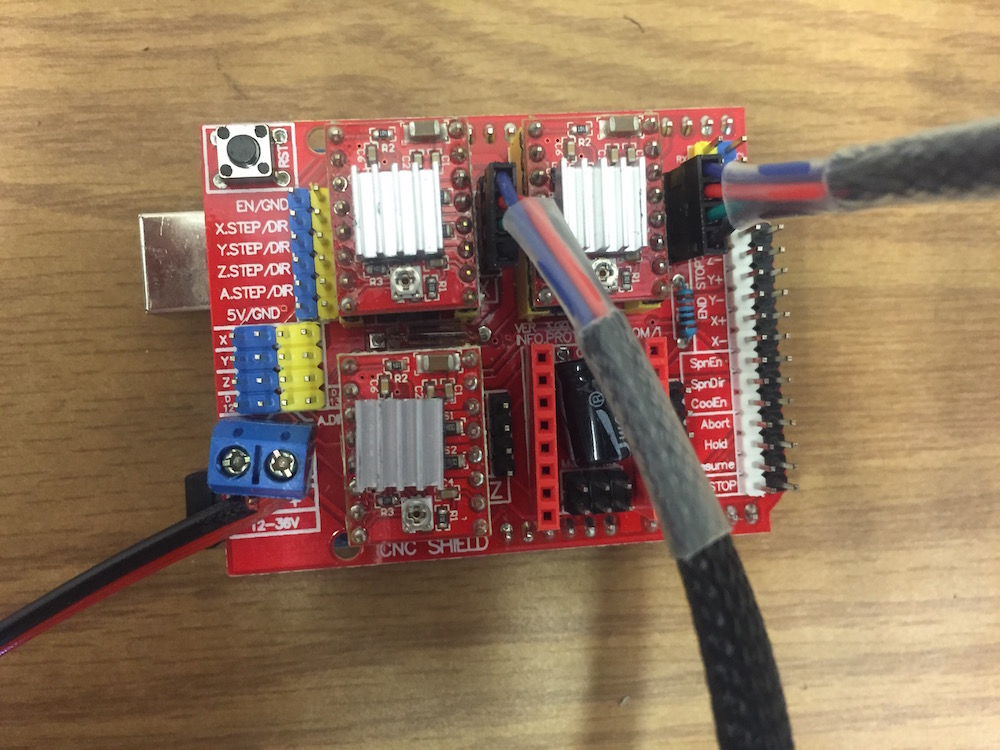
- Stepper Motor Control Board
- The Motor Drivers draw power from the 12-36V line input on the Stepper Motor Shield.
- Stepper Motors
- The motor direction will reverse if attached incorrectly. Make sure the X and Y axis motors are connected as shown below.
Software
The machine runs Grbl on the Arduino, to drive the stepper motors. It takes G-code inputs via serial communication thru the command line, or can accept a CAM program from a compatible G-code sender.
To get started with G-code, develop a CAM file on your prefered software package, and post process using a compatible cps file. Autodesk has included a Grbl-compatible option in HSMworks and Fusion360.
Because the Y-axis position depends on the workpiece diameter, remember to calibrate the system by adjusting the steps/mm value for the Y-axis using $101=[val]. The parameter values [100, 101, 102] correspond to the step size for [X, Y, Z] respectively. To see other parameters, use $$.
For more information on the Grbl project, visit:
Part 3 - Future Work
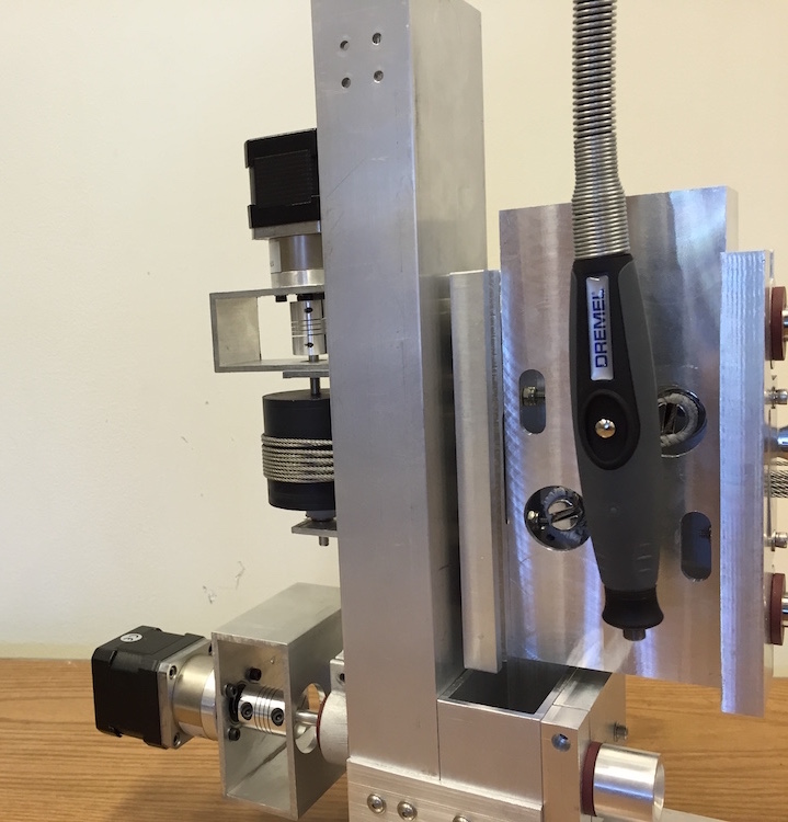
As part of 2.77, I have built the core of my CNC Engraver. With the design tested and working, my next steps will focus on adding the third and final axis: the vertical-travel Z-axis with the tool holder. I am planning to use a Dremel Flex Shaft as my cutter spindle, which will be mounted on the Z-axis carriage, and thru the latter to the X-carriage, as such:
Of course, there's always room for improvement. Here's a list of my next steps for this project:
- Z-axis
- I will be working on the Z-carriage and tool-holder design, integrating these onto the current system.
- Stepper Driver Boost
- The Motor Drivers are currently set to the default current limit, usually listed as ~50% of max. The NEMA-17 motors I have installed on the machine are rated for up to 2A, higher than the limit presently set on the stepper driver boards. Since giving the motor full access to the allowable current may help reduce skipping steps, I plan on adjusting the system for this purpose.
- Tail-cone Live Center
- As part of the rotary axis, I still need to build a form of live center to be able to lock workpieces on the machine.
- Spindle Attachments
- I will also be looking into other methods of holding workpieces on the Y-axis spindle. Building the option to use a mandrel or clamping parts on a chuck could prove helpful when machining hollow-core parts or materials that would otherwise slip on the cone clamp.
- Limit Switches
- In order to add homing and hard-limit triggers to the control system, I would like to integrate limit switches in the future.
- Electronics Enclosure
- As I am looking into running the system via a browser-based application, I might replace the Arduino Uno with a stacking Raspberry Pi, Arduino Nano and Stepper controller package. In either case, I will need to build an enclosure for the electronics in the final configuration.
- Software Tuning
- I have reached the point where the machine operates well, and the motion appears smoothly. During early testing and characterization, however, I've noticed some variability as the system wears in and settles. Furthermore, I have noticed there is some small amount of lost motion. This could be due to lost steps during acceleration, for example. I will need to review my software parameters and make sure they are optimized for the machine.